
 Hamann's baby!
I know what the button does, but I was wondering how it actually works? Are there two different settings in the EML and the switch only selects from one to the other? Does the CSi have two EML modules and the switch selects one or the other? Two different EML chips controlled by the switch?
I'm familiar with switchable 'chips' on the ford side where you can have a race tune and street tune on the EEC-IV and all controlled with the flip of a switch. I was wondering if this is comparable to how the CSi switch works.
CB42366 - 1991 850i 6-speed. Brilliantrot & Black Nappa Leather
CD00144 - 1994 850CSi. Hellrot & Black Nappa Leather
My other projects:
Supercharged Tbirds, V8 Tbirds, V8 Mustang Convertible, Audi V8 Quattro & Audi S8
Member
That's correct.Originally Posted by CaifanSC

Hamann's baby!
Lightning fast reply, thanks Revtor...
To be honest, the reason why I was thinking about this is because I was wondering if this can be done to other 8's. As far as I can tell from BMWfans.info there is a diffident EML module, but I have a feeling that it's not as easy as swapping EML's and adding a switch.
CB42366 - 1991 850i 6-speed. Brilliantrot & Black Nappa Leather
CD00144 - 1994 850CSi. Hellrot & Black Nappa Leather
My other projects:
Supercharged Tbirds, V8 Tbirds, V8 Mustang Convertible, Audi V8 Quattro & Audi S8
Member
Well, one problem is that the 850CSi EML has no support for automatic transmissions and that it requires ASC+T. So that leaves only M70 6-speed owners. A second problem is that the 850CSi has updated DMEs. The M70 in the 850i/850Ci uses version 1.7 whereas the S70 in the 850CSi uses version 1.7.1. The EML engine speed limiter on the 850CSi is gear dependent. It's unclear to me how exactly this works (the electrical troubleshooting manuals seem to be incomplete for the 850CSi EML and DME), but I doubt the 850i/850Ci has provisions for this.
www.wokke.de
A customer of mine in Munich managed to install it in his 6-speed M70 powered 850. He can now switch between OEM and my chip. But please don't ask me how exactly he has done it.
MAX@FINEMOTORING.COM
I've forgotten the details, but you can research the WOT limitation on the EML and probably figure out a workaround. Maybe grounding pin 62, or 42? The EML won't go to WOT under 4200 RPM by design, and I suspect that both the Motorsport division and Wokke's chip guy figured this part out as part of the improved throttle response maps.
How come the middle half of any project always takes the most time?
Hamann's baby!
So it is possible! Research time
Ok Wolf, I won't ask you how...but any info you have would be great! Do you think your customer will mind I ask for his/her contact info?
CB42366 - 1991 850i 6-speed. Brilliantrot & Black Nappa Leather
CD00144 - 1994 850CSi. Hellrot & Black Nappa Leather
My other projects:
Supercharged Tbirds, V8 Tbirds, V8 Mustang Convertible, Audi V8 Quattro & Audi S8
Member
^Yes please!! Any info would be great!
2.8 Z3 coupe + 6 speed || 200kW electric 1970 Jaguar XJ6
www.wokke.de
I'll check back with him.
Member
Hi @All,
I wrote a small description for you.
How to switch between two engine setups
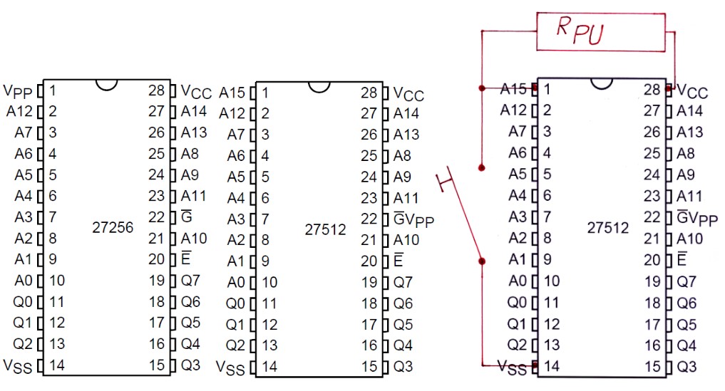
In the M70/S70 DME and EML ECUs 27256 Eproms are used to store the engine setups. Those are Eproms with a capacity of 32 Kbyte. (256 KBit (32K x 8) UV EPROMs)
With a capacity of 64 Kbyte, a 27512 Eprom is twice as big. As you can see in the attached picture, opposite too the 27256, the 27512 has a 16th address terminal at pin 1. This allows the cpu to address the hole 64 Kbyte Memory, or you to divide the 27512 in two banks of 32 Kbyte each. The rest of the 27512 is pin-compatible to the 27256 for reading purposes.
As you can see in the attached picture, with a pull up resistor (Rpu) of about 5 KOhm and a simple switch, you can choose between the lower/upper 32 Kbyte bank, and with this, between two different engine setups. The resistor pulls the address-line #15 (Pin 1) to a TTL high level, if the switch is open, and if the switch becomes closed, pin 1 receives TTL low level.
I would realize a setup like this, using two 28 pin precision-dil-sockets, to connect the resistor and the switch-cable too. Important is, to not connect pin 1 to the circuit-board of the ecu, since this may be connected to system ground. This would not result in any damage, but prevent the 27512 from switching between the two memory banks.
How the data come into the new 27512 Chip
With a Eprom-Programmer you should read out your original Eproms and save the data in .bin-files. Later you have to program your first .bin-file to bank one of the 27512, starting with address hex 0000 up to hex 7FFF, and your second file, starting from hex 8000 up to hex FFFF.
Best regards
Joachim
Last edited by ArnoNym; 09-28-2011 at 04:20 AM. Reason: Uppercase the Hex-Numbers for better readability
Member
BMW CCA Member
On a similar note.. When I shift my 735i/850i (4HP22/4HP24) into 3, it goes from E-D to S-3.
On standard chips, or on Shogun chipss, does the Sport mode change the engine performance in addition to the shift points?
1) Is it possible to get M-D ? (Manual mode in 4th)
2) Is it possible to get S-D ? (Sport mode in 4th)
As many of you know, the transmission range selector switch encodes the current gear..
With 4 bits, there can be 16 possible combinations, only 7 are used..
L2 is high in Park and Neutral (for starting), and sent directly to the start signal..
L4 is high in R and D but no other gears. (Auto/Economy?)
Has anyone tried any non-standard combinations of the bits? Obviously most of them will throw limp home mode if wrong, and most of them will show a blank indicator... But I wonder if other modes are possible.. S-4 would be nice..
Also, my 4HP24 and transmission range selector switch from 1991/1989 changed over the years... I ordered a transmission range selector from Charlie that was the wrong part (I have an extra 'yellow' switch if anyone needs one)
Last edited by EEDegreeToDrive; 09-27-2011 at 11:15 AM.
'89 735i, '91 850i, '81 MB 380SLC (For Sale), Tesla Model 3, and VW Passat TDI -- Yes, I still repair General Modules, DM for info!
Hamann's baby!
First of all, thanks a lot for your reply Joachim!
So if I get this correctly, one would need to:
1- get the double-capacity 27512 chip to replace the 27256 originally in the EML (or does this have to be done on both DME's too?)
2- Program the 27512 according to what you stated above (essentially half OEM profile, half upgraded profile...for example, Wokke chip).
3- Add the resistor between pins 1&28 of the 27512
4- Add connections from Pins 14 & 1 of the 27512 to Switch...what kind of switch did you use? I'm hoping the CSi EML switch can be used as it will look stock.
CB42366 - 1991 850i 6-speed. Brilliantrot & Black Nappa Leather
CD00144 - 1994 850CSi. Hellrot & Black Nappa Leather
My other projects:
Supercharged Tbirds, V8 Tbirds, V8 Mustang Convertible, Audi V8 Quattro & Audi S8
MAX@FINEMOTORING.COM
Alternately, you could investigate this option-
http://www.millerperformancecars.com/war-chip.html
How come the middle half of any project always takes the most time?
Member
1 This depends on what you intend to do. If you only plan to remove the Vmax limiter, or you want a more sportive throttle response, you may only work on the EML. If you want more power out of your engine, you need to work on both DMEs.
2 Right!
3 Right! Pin 28 (Vcc) has 5 Volt plus, pin 14 (Vss) has system ground and pin 1 is the address-line.
4 A simple closer switch is necessary. I dont know what kind of switch the CSi EML switch is, but I guess it should be usable.
www.wokke.de
@ArnoNym
Danke für die tolle Erklärung.
Hamann's baby!
Was fiddling around with the CSi the other day and noticed one thing that was not mentioned in this thread. Maybe Joachim or anyone else familiar with this can give some input.
What would it take, or, is there a way of also having the "S" come on in the gauge cluster when the EML switch is flipped to "sport"? Just like it happens on the CSi?
CB42366 - 1991 850i 6-speed. Brilliantrot & Black Nappa Leather
CD00144 - 1994 850CSi. Hellrot & Black Nappa Leather
My other projects:
Supercharged Tbirds, V8 Tbirds, V8 Mustang Convertible, Audi V8 Quattro & Audi S8
Member
Revtor.....The gear dependent RPM is controlled in the DME by means of few bytes. I added some code to my Tunerpro File to allow me to set them anywhere from 0 to 10,200rpm (MAX for 8 bit Ecu)
Member
You would need the EML switch and recoding of the EKM module to automatic transmission (function "GETRIEBE_TYP" set to "automatik_5_gang" and "GETRIEBE_ANZEIGE_PROG" to "aktiv").
I'm not sure the wiring for the EML switch is present on non-850CSi E31, but the EML switch is actually a toggle switch that either pulls pins 9 & 11 of connector X39 on the EKM to ground (comfort) or pin 52 on the EML (sport). Pins 9 and 11 of connector X39 on the EKM control the gear program display for use with automatic transmissions. When coded for manual transmission these inputs are ignored, so in order to get a simple way to display an "S" in the instrument cluster the BMW engineers decided to code the EKM in the 850CSi for an automatic transmission and hook up pins 9 and 11 to the EML switch.
That makes sense because there's certainly not something like a gear position switch on the 850CSi.
Member
Not being especially familiar with EMLs, EKMs and so forth, this is my expression while reading most of this thread.
depositphotos_1346938-Amazed-man-holding-tobacco-pipe.jpg
 Member
I get a kick out of reading older threads on this forum, and this was one that was intriguing.
More so after I found that there was a product that looked like it could make it a plug and play solution.
The Moates 2Timer allows for the use of a 64kb rom, and switching between two 32kb address blocks.
http://www.moates.net/font-size-12timerfont-p-80.html
I used a moates burn2 device to dump a .bin file of the OEM EML chip, and the Wokke EML chip.
Next, I installed TunerPro, and used the Bin stacker tool to append the OEM rom to the Wokke rom (I.e Wokke at position 0, and OEM at position 1).
Next, I burned the resulting 64kb .bin to the 27SF512 rom that came with the 2timer.
Finally, I installed the new rom, and 2timer socket back onto the EML board, and closed it back up. It fits like a glove!
Shown here is the ground wire.
Left to do:
Extend ground wire into the cabin through the grommet behind the EML/DMEs
Figure out how to connect the EDC switch that Im temporarily going to use in lieu of an EML switch
Stretch goal:
Reprogram my EKM from manual to auto and wire the two pins mentioned in the thread to enable the cluster bulb illumination. Ive read that this may be tough with a 1991 car.
Sent from my iPhone using Tapatalk
Member
Used revtors new tools this evening.
First, I downloaded my EKMs configuration (trace file) using EKM coder.
Then I downloaded NCS Expert, the e31 daten for NCS Expert, and the newest NCS Dummy.
I ran NCS dummy, and pointed it to the NCS Expert daten folder, which included the e31 folder, selected the e31 chassis, and the trace from EKM coder.
I was then able to edit the two transmission options, from manual to auto,
Finally, after saving the modified trace file using a different file name, I uploaded back to the EKM.
Next, Ill tackle wiring up the switch!
Sent from my iPhone using Tapatalk
Member
One thing to consider when connecting mechanical switches to digital circuits is SWITCH CONTACT BOUNCE. Adding a simple resistor capacitor filter should be enough.
Photo on 3-28-21 at 8.36 AM.jpg
Member
Having read a couple of articles, I understand the concept, but I am not ready familiar with electrical diagrams. It will be enough of a head scratcher for me to work out which pins of the edc switch to use for the EML switching and cluster display.
When I get to that point, Ill see if I can integrate what youve suggested.
Sent from my iPhone using Tapatalk
Member
I would think the input pins would have some built in filtering (or more properly, delay) for switch bounce...
Member
The previous diagrams show connecting directly to address pin of an EPROM, so... Nope.
 Posting Permissions


 Reply With Quote


Bookmarks