
 Member
For M50 series see http://forums.bimmerforums.com/forum...d.php?t=879273
I have worked long and hard to get my car up and running on Megasquirt and to save you the massive headache and endless hours of research I have decided to share my experience. If you play your cards right, you can have a complete standalone with no afm and complete spark control for less than that silly MAF kit.
-Hari's MS2 w/ GM wasted spark coils
First you will need to gather all of the necessary hardware and tools. I highly recommend DIYautotune.com and its best to start to get to know your local radioshack. Set your goals for the build so you will have all necessary hardware. If you want wasted spark coils, order 2 extra VB921s. If you want boost control, order the “kit” with the MS. If you will be adding any extra features at all buy a few solder cup db 9 connectors.
***make sure to print out the assembly and tuning guides***
-First you must obtain a 55 pin Motronic ECU (153,154,173,179, etc…). You can use the one in your car because you will never need it again but if you are a huge pansy you can easily obtain one for under $50 on the internet auction thingy.
-Order an MS1 or 2 with the version 3.0 board without the case. It will save you $10 and you are not missing a thing. Just email DIYautotune and Mat will hook you up.
-If you do not have a serial port on your laptop, purchase the USB adapter from them (trust me) you do not need the internal one for reasons we will discus later.
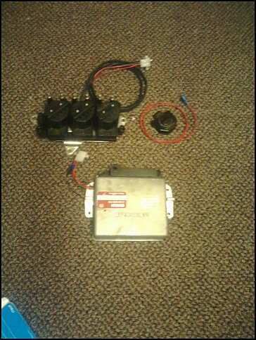
-Order the 3 wire bosch idle valve board from Glensgarage.com (you can build the circuit in the proto area but it is the biggest pain in the ass and not worth the $8.00 you would save. If you dont want to shell out for the board:
-Order a wideband o2 sensor before you even start the build. In this write up I will only be discussing the LC-1. Just buy it, you can not get better for the price. Besides, then you don’t need to make a tuning cable (discussed latter).
Go to radio shack or if you are an experienced electronics builder use digikey, etc..
-Soldering Iron (pencil type is fine)
-0.030 Rosin solder
-Solder wick (copper braid) for fixing ****-ups
-Package of 2n2222 npn type transistors
-Assortment of ¼ watt resistors (330, 1k, 7.5k, 10k, etc..)
-two potentiometers (10k and 50k)
-Female 3/32 3 way stereo plug (not the in line type but the case mount kind)
-assorted colors of 20 gage stranded wire
-about a foot of 2 core shielded wire
Go to your well endowed hardware store
-Digital Multi-meter
-Yellow crimp style ring connector (for making a common ground)
-Small wire clippers and needle nose pliers
-Drill and various bits
-Dremel comes in handy but not necessary
-2.5 mm vacuum tubing and a T – fitting
-Nylon spacers and longer nylon machine screws. I forget the size but they just need to be long enough to mount the board to the case. I believe they were M3 or M4. Shoot for the same size as is included in the kit
Lets get started.
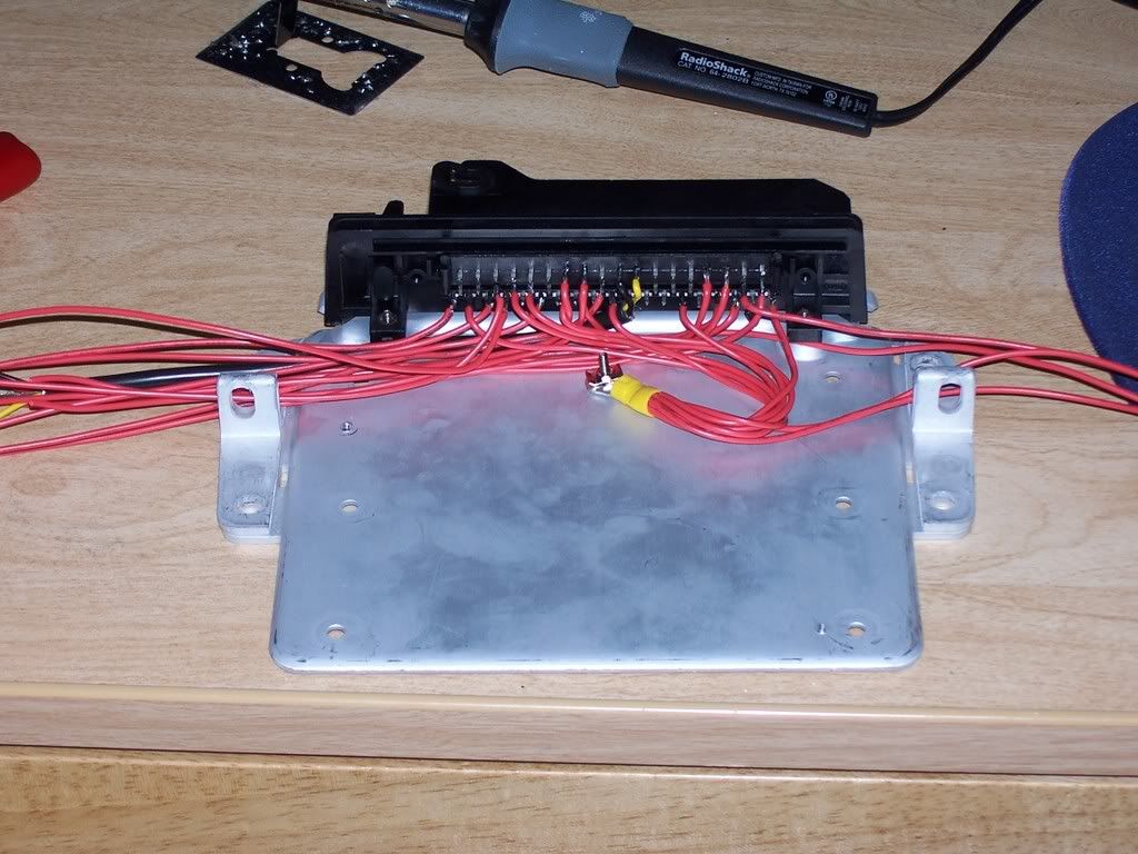
Start by gutting the old Motronic case. Remove the cover and all bolts on the bottom. The board should separate from the aluminum with the connector attached. On the bottom side, the metal flanges where the bolts that hold the connector to the case go through need to be ground off. Only grind off the bottom and don’t go psycho on the thing. We will reuse the same bolts to hold the connector to the case. Next, snip the leads on the back side leaving about a ¼ inch of metal. Just remember that the longer they are, the more brittle and susceptible to shorting they are. The connector should pull free of the board.
Next we will drill all of our mounting holes. Take the new V3.0 MS board and lay it with the 37 pin connector on the left (w/ the connector facing away from you) and the 9 pin on the lower right. Pick at least 4 good mounting holes on all 4 corners. Remember that the ones around the DB37 and DB9 connectors will not be used for anything else. Then drill one hole about the midline and ¾ inch from the 55 pin connector (this is for the grounding point)
Board Build
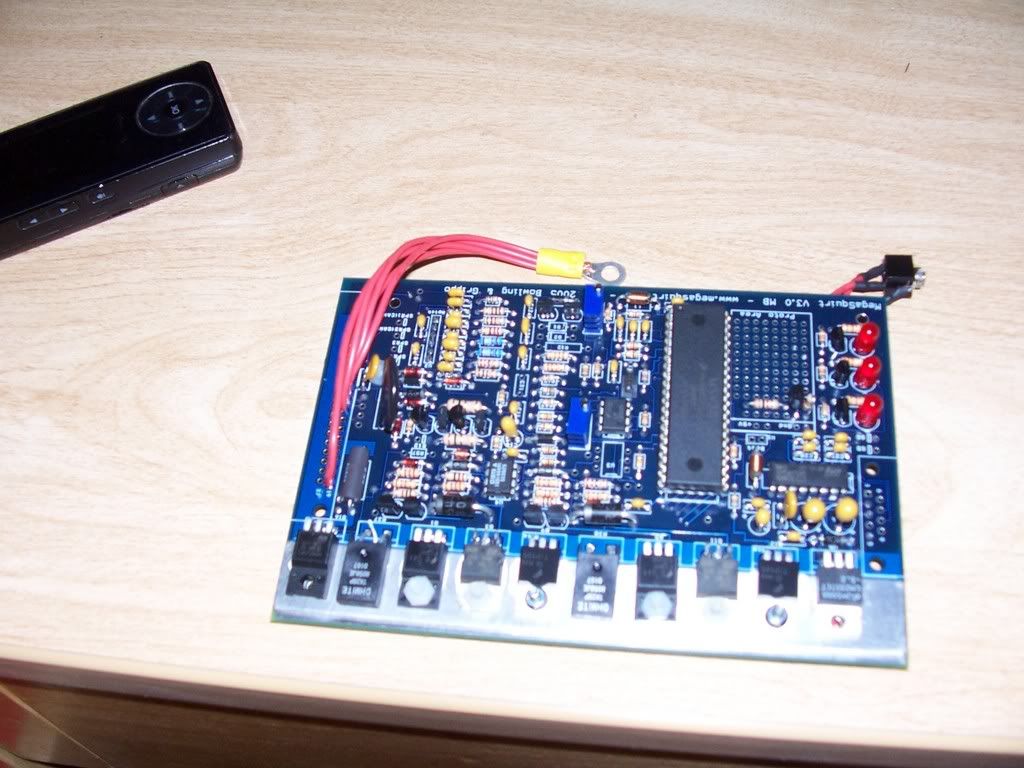
Next you will assemble the V3.0 board.
-not so intimidating, is it.
-Follow the instructions from the Megamanual. But DO NOT install either the DB9 or DB37
-You do not need to install the coil driven tach signal, or the hall circuit so skip step 50.
-on step 52, jumper VRIN in to TACHSELECT and TSEL to VROUTINV
-In the proto area, put a 330 resistor connected to the top side of R26 and
IGBTIN and jumper IGBTOUT to IGN (if you are going wasted spark, skip this and skip step 65)
-Also in the proto area, you must build the tach out circuit. Use the diagram from the MS1extra manual and send the signal wire to the IAC1A output near the DB37
-instead of a 50k pot use a 100k
-cut at least 5 wires about 6 inches long and strip bout 1/8 in from one end. Solder these to pins 8-19 of the db37 (straight to the board) and combine them in one of those crimp style ring connectors (make sure they will reach that grounding point on the case) and make it as neat as possible. Excess wire is not desirable. We are working with limited space.
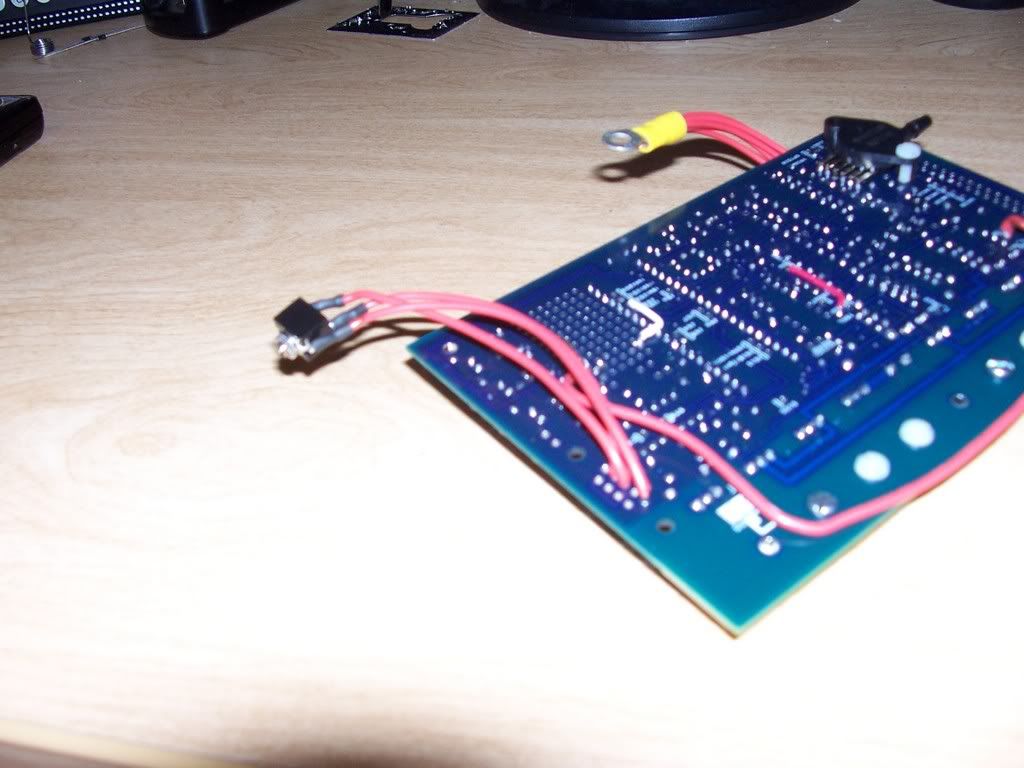
Now we need to make a serial port. I used to solder on the db9 connector and just cut a hole in the side but that wouldn’t allow a tuning cable to be hooked up all the time. The ECU would have to be removed for tuning. Instead we will use the tuning cable that came with the LC-1 (you bought one, right) The Stereo plug connector will mount to a hole you will drill in the Case cover on the right side above the mounting bracket. (for easy access)
-On the board, solder three wires (about 4 in. long) to pin 2, 3, and 5. P
Pin 5 solders to the proximal prong (the one that touches the base of the plug)
Pin 3 is the distal end of the prong
Pin 2 is the middle
The board is now complete so we will now start to wire up the connector.
-you will need about 24 wires cut to about 1 foot in length. Strip about ¼ inch from one end.
Place one wire on all of the following pins (except 16 and 17, they need two each) and the following number is the pin on the BD37 that it corresponds to. Do the 55 pin connector first. Combine all of the grounds into a crimp ring connector so that it will reach your ground point. Bolt the 55 pin connector to the case. Mount the board and then you can measure the wires for length. Fold them over to the left and then over to the DB37 connector. Leave the board as visible as possible. Cut the wires with a little slack in them and strip about 1/16 inch from the end. You do not want too much wire sticking out the bottom.
***Before you solder any wires tho the 55 pin, place the 1n4001 diode across pin 18 and 36 (banded end towards 18)
1 Coil- 36
2 GND
3 Fuel Pump- 37
4 IAC close- Glens Board
5 Evap Purge- GND or a control circuit
6 Tach signal 25
10 GND
14 GND
16 Fuel inj. 1,3,5- 35,34
17 Fuel inj. 2,4,6- 33,32
18 Constant 12v- 1n4001 diode (no wire)
19 GND
22 IAC open- Glens Board
23 GND
24 GND
26 GND
27 Ignition switch (12v) -NPN Transistor
28 o2 sensor- 23
36 Relay control- NPN transistor and other end of diode
37 12v Power Supply- 28
44 IAT- 20
45 CLT- 21
47 VR sensor blk- 24 (shielded)
48 VR sensor yel- 7 (shielded)
52 TPS 5v- 26
53 TPS Sensor- 22
You should probably use various colors. I've just done it so many times i could do it blindfolded.
When you combine the grounds from the 55 pin, place 2 more wires in the bundle. One is for Glens board and the other is for the Main relay circuit.
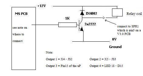
-Pin 18 and 36 also go to the relay control circuit. They will be loose from the rest. These three wire will connect to a 2n2222 transistor to activate the main relay.
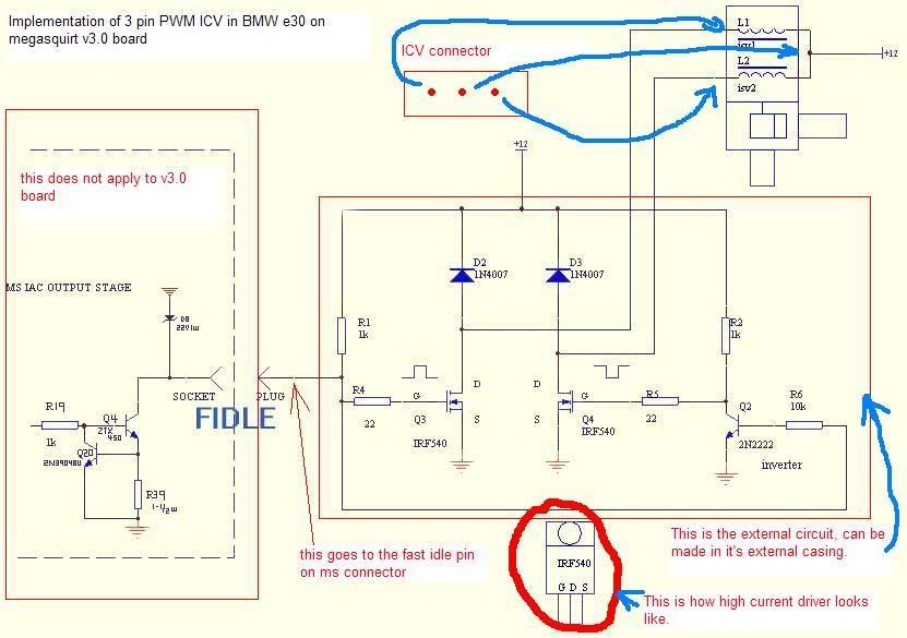
These diagrams should help in the construction of the relay circuit
-The emitter connects to the ground wire
-Th base connects to pin 27 with a 7.5k ohm resistor in line
-The Collector connects to pin 36
-Solder the 1n4001 (D1) diode from MS (that was not used because we didn't install the hall circuit) across Pin 18 and 36 with the banded end towards 18
Secure the transistor to the case with hot glue or silicone caulk. It would be a good idea to cover the entire back side of the 55 pin connector in silicone caulk once the harness is complete. This will also help wires from accidentally breaking loose if they were not soldered very well (shit happens, plan accordingly)
-For the PWM idle valve board from GLensgarage you will need to bring out the spare GND, 12v from s12c on the bottom side of the board, Signal from pin 30 of the DB 37, and the IAC open and close signals from the 55 pin. Leave the wires fairly long. The board is going to be bolted to the lid of the case and you want to have some room to play with if you ever need to work on the board again. You can also bring the signals out from R29 and R27 to the spare spots on the board for if you ever decide to add Wasted Spark coils (if you built the unit for single coil).
Sensors
For m30/20
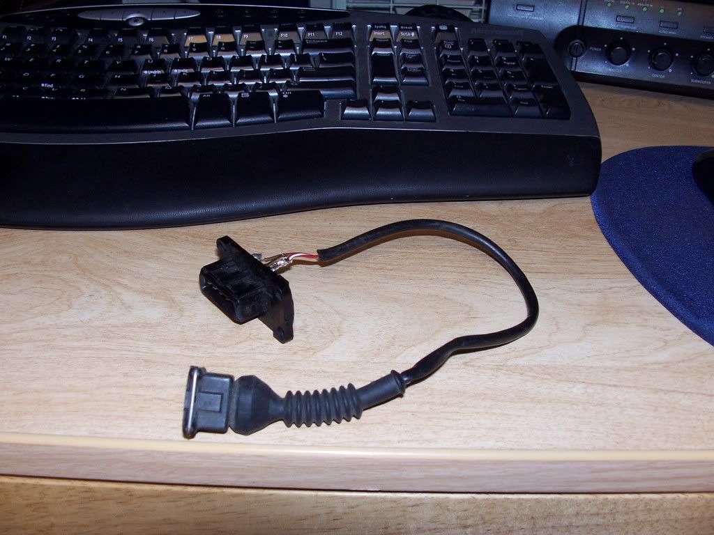
The stock IAT can be used but i recommend that you replace the AFM with straight pipe and place a bung for a GM open element sensor. Just gut the afm for the plug or hack the connector for the wires. (GRY/BLU and GRY/VIO) Paint/powder coat it black and call it done.
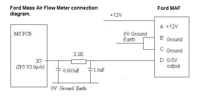
MAP
If you already removed the AFM you could use an external MAP sensor if you don't want to run a vacuum line to the ECU. Use the afm signal wires and share the ground with the IAT sensor. Run a signal line from the input pin on MS (varies with code) to pin 7 on the 55 pin and 5v from the proto area to pin 12
Signal is GRY/YEL
5v is GRY/WHT
GND is shared with IAT on GRY/BLU
The same thing can be done with a MAF but only some codes of MS2 support it (not MS2extra) and MS1 extra. Check first
For the m20/30/88 series engines, you will also need a variable TPS. Though it is possible to run the car without i strongly recommend one. The m20/30 auto TPS will work but will need a pigtail for the connection. The S/M5x TPS will also work but will need an adapter plate to fit the TB. I think M5W made a few extras, but they are not hard.
The instructions for figuring out the pins for your TPS are in the Megamanual. I will quote the paragraph when i find it. The wire from your stock harness are as follows:
BRN/ORG is GND
BRN/BLK is signal
BRN/BLU is 5v reference
***If you are using the M50 TPS, you only need to swap the BRN/BLK and BRN/ORG around. The stock connector can be used
"MegaSquirt uses the throttle position sensor (TPS) to determine when the engine is at or near full throttle (to shut off feedback from the O2 sensor), when the engine throttle is opening or closing rapidly (and needing an accel/decel enrichment), and when the engine is flooded and needs to be cleared. Some people have managed to make their engines function reasonably well without a TPS. This is not recommended with the standard code, however.
You will need a TPS that is really a potentiometer and not a switch. Many older cars had idle or WOT position switches instead of a real TPS. A real TPS gives a continuously varying signal with changing throttle. There are two wires on the external wiring schematic that go from MegaSquirt into the TPS sensor. These two MegaSquirt wires are +5 Vref signal and a sense line. There is a third wire going to ground. Assuming that you have a proper potentiometer TPS, then +5 Vref goes to one side of the pot, the other side goes to ground and the sensor line is hooked to the wiper.
To hook up your throttle position sensor (TPS), disconnect the TPS, and use a digital multi-meter. Switch it to measure resistance. The resistance between two of the connections will stay the same when the throttle is moved. Find those two - one will be the +5 Vref and the other a ground. The third is the sense wire to MegaSquirt. To figure out which wire is the +5 Vref and which is the ground, connect your meter to one of those two connections and the other to the TPS sense connection.
If you read a high resistance which gets lower as you open the throttle, then disconnected wire is the one which goes to ground, the other one which had the continuous resistance goes to the +5 Vref from the MegaSquirt, and the remaining wire is the TPS sense wire.
The throttle position sensor is used for flood clear mode and EGO enrichment, as well as accel enrichment" -From Megamanual
O2 sensor.
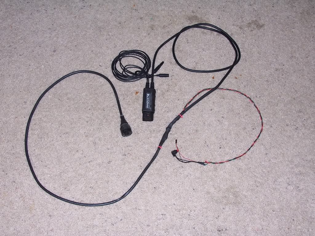
As stated earlier, i highly recommend th LC-1. Place it in the stock sensor location and hack off the pigtail from your old sensor. If you ever want to go back to motronic, the LC-1 can simulate a narrow band.
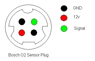
Wire the LC-1 straight in to the pig tail and seal it with heat shrink
Pin 1- Sensor GND- GRY
Pin 2- Signal - BLK
Pin 3- GND- White
Pin 4- 12v- White
Use an ohm meter to determine which white wire to use for power
From LC-1
BLU and WHT are both GND- combine them with a spare black wire about 4 ft long and conect them to the GND wires on the Bosch connector
RED wire is power, conect it to the 12v white wire
BRN wire is output 1 and will go to the BLK wire
BLK wire is the calibration wire. Connect about 4 ft of RED wire to it
YLW wire is output 2. It can be used for a guage or leave it there and tuck it in out of the way
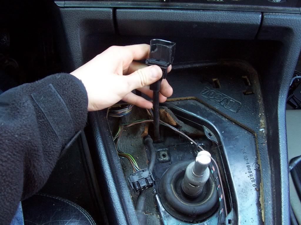
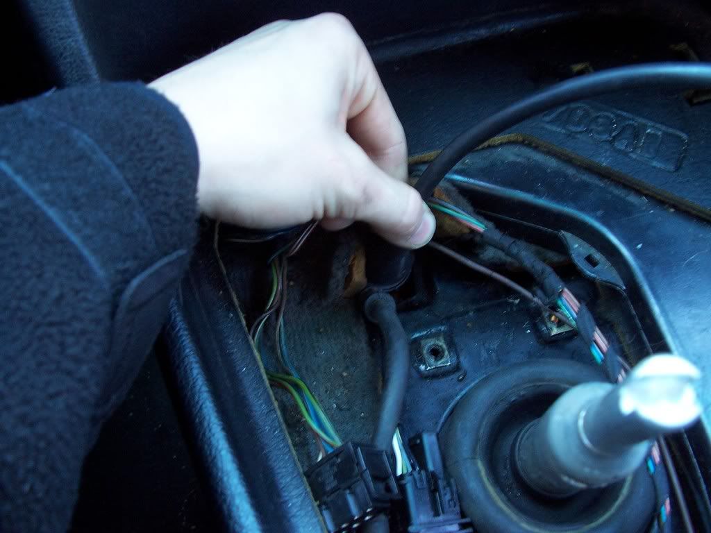
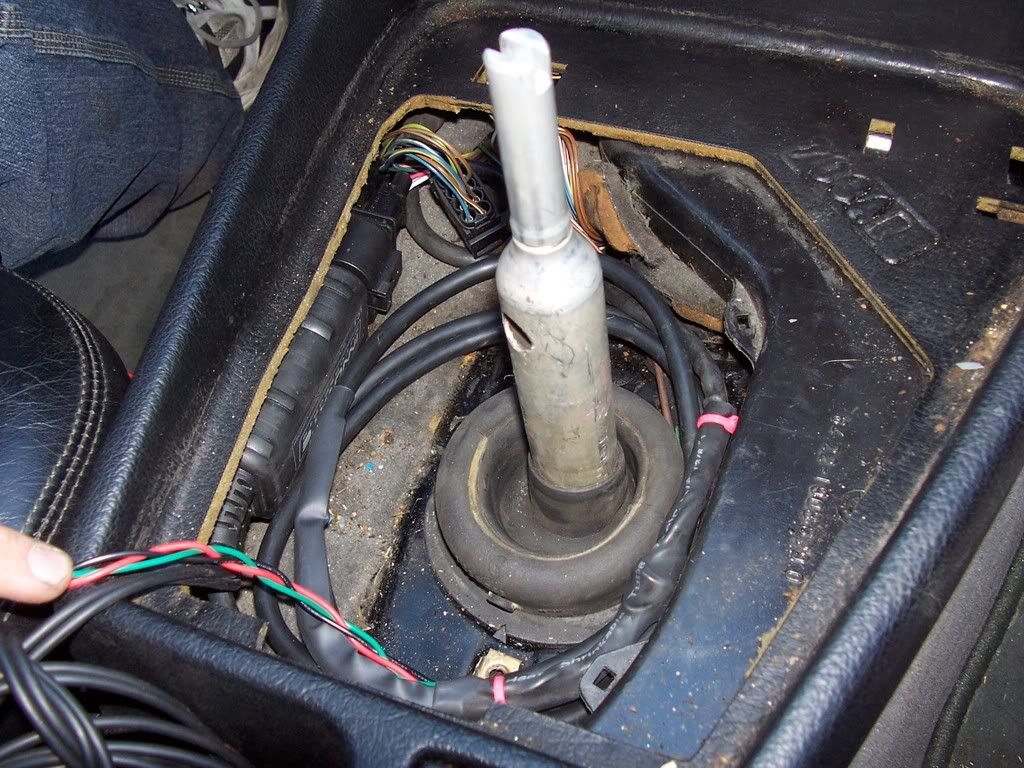
The spare BLK and RED wires you attached are for the calibration button. Run them into the cabin of your car ( i ran them up through the shift boot and keep them hidden under the shifter. Connect the switch and LED to the two wires as outlined in the LC-1 manual. The Red wire on the LED connects to the RED wire you brought in. The switch wont matter. If you want you could use any led and switch you want and make a nice mounting plate for in front of the shifter for other switches and gauges. I made a plate out of wood and put my launch control, LC-1 switch and LED, and a USB port for easy access and will add things as i go. It looks very nice.
Drill a hole in the case for the vacuum line and a small one to mount the serial connector. If you have installed any options like launch or boost control you will need to mount a db 9. If you went wasted spark, I would recommend a completely separate port. (so 2 db9s of opposite gender) one for spark, and the other for I/O
Tap into the vacuum system for your car with the T connector. The best way is to use the lines from either the FPR or the one running to the underside of the intake boot above the harness. Cut the hose and place the T in. Run the Vacuum line into the ECU box.
Now you are ready to power it up for the first time. After you have installed and configured Megatune you can download your firmware. Do not use the base codes. Go to MSExtra.com and go to the MS2 development section and download the latest beta (unless you have MS1). In the file there will be 2 .ini files. Double click both of them and follow the instructions (make sure you disconnect the coil first)
If I can figure out how to host a file, I will post up my msq file for anyone with an m30 and it should get any m20 or s38 running.
Ryan Nimick (Goathumper)
Oct 23, 2007
Me:

Last edited by jamesdc4; 02-13-2008 at 10:18 AM.
Member
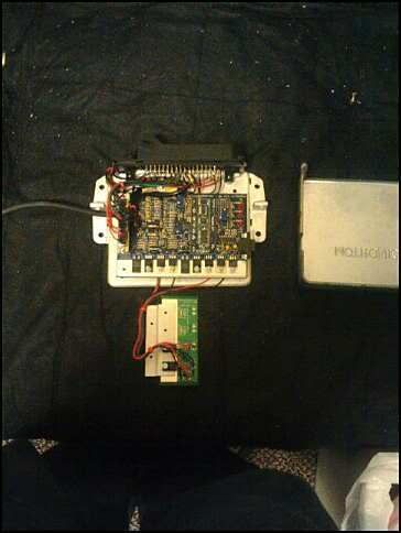
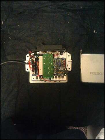
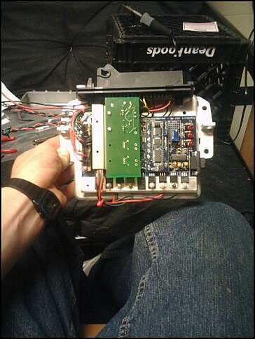
Pics will be inserted soon, Wasted spark how too will go up some time this week.
Ryan
Member
How much would you want to build one for someone else? ($)
Member
500 for MS1, 550 for MS2, $50 core charge if you don't send an ECU. All other options can be negotiated.
M50 coming soon...
Last edited by Goathumper; 10-23-2007 at 04:05 PM.
I am TD
I haven't read over this yet, about to go play soccer, but feel free to send me the msq file and I can host it. tldavis6@ncsu.edu
Member
BMW CCA Member
I just want to vouch for Goathumper. I bought one of his MS2 PlugNPlay setups and will be installing it on my car as soon as it's out the shop. He is legit!
License Revoked
You do M50 525's also? It looks worthwhile to get one from you to be sure it works rather then save 50$ by diy this piece....hmm.
Member
Wasted spark will look like this. Just mount the VB921s on the case below the board.
I am TD
Also for those of us with M30 manuals, a variable TPS is needed off either a 535 automatic or a M50 TPS can be used, but a mounting bracket will need to be fabbed up.
Member
yea, i am slowly adding things i forgot, thatl go right up.
Kesslerbmw
subscribed..
Ian
hmm.. I know you were looking to do this without the MAF conversion. And Hari uninstalled his MAF for this......BUT.. can this be done with the MAF conversion? Will the benefits be more?
Member
MS uses MAP for fuel calculation, put some straight pipe in where that ol' flapper was for ZERO restriction.
I am TD
MAF can be used with MS, just a PITA to do so and much simpler to go MAP.
Member
MAF can not currently be used with MS2 extra, you would have to use MS1 or microsquirt code. A step backwards....
Ian
Can you tell me the benefits of MS vs MAF.. considering that the MAF is already installed. Basically, why would I want to switch?
ballin' on a budget
I will send you an m60 ECU to play with if you pay shipping
BMW Man
Member
yea, i'm up for that. I've always wanted to play with a v8 but there doesn't seem to be much interest.
Member
The MS is a full standalone with unlimited potential. You can completely control fuel and spark and even eliminate that nasty distributor and expensive wires for less than a new cap and rotor. Add ons are almost limitless. You can control 2 stage nitrous, tabled boost control, launch control/flat shift, Power anything that can be activated via relay set to any 2 parameters you want (fan, vanos, shift lights, etc..), you can run alternative fuels (c16, e85, etc...), Plus the cool factor.Originally Posted by E34N

Ryan
I am TD
Here's the way I look at it- if I want to turbocharge, I'm locked into Millers tuning. There are more than a few M30s around with MS and turbos.
EDIT: when I turbocharge
ballin' on a budget
So I'm a noob at this. Tell me if I am right
I send you my ECU, you do your thing with it and send it back. I download a program on my laptop and hook it up to the car. I can adjust fuel/spark from there.
BMW Man
Member
yea, in a nut shell. I have the M30/20 down to a science. Currently setting up an M5 and have a proto version for the M50 (i am getting a 525i this month) and hope someone with an m60 would play victim/volunteer.
Remember, the goal of my setup is to make as little changes to the harness as possible.
Ryan
Member
this looks like it could be pretty amazing stuff... man you are a genius
Member
On a scale of 1 to 10 how much electronics knowledge is needed? 1 being no knowledge and 10 being a qualified auto electrician.
This is nice
E3.4
Member
I just got my MS2 from ryan hooked up in my car, goin to start it tonight. He builds a quality ecu, looked inside last night lol. Clean soder job and nicely packaged. He is very helpful and will always help you out when your stuck. Did i mention i'm running it on my M5 ? Helped me thru setting up the whole thing and when the ecu came there was wiring and every connector i needed. If you wanna do this , you can put your trust in him. Knowledge without ignorance is hard to come by, but if he dosn't know the answer he'll look for it. I paid for the ecu, tps sensor, and innovative wideband what it would have costed me for a stock MAF for my car. And this isnt a hack job, so if ever needed i can go back to stock but simply swapping out the ecu and changing a couple plugs. Clean install.
And theres a TO4 70 trim waiting for me in ohio at my families place
Remote Mount with standalone ? OH YA !
Last edited by M5W; 10-24-2007 at 08:38 AM. Reason: spelling
 Posting Permissions


Bookmarks