
 Member
Originally Posted by Fiziks
 Well, I put mine in tonight. Got the flicker, and the code so this sucks balls. I can stand the flicker as it's very faint. However, the fault aggravates me. After reading more of what m5shoot says, I may opt for the more expensive ones-definitely don't want any equipment fried.
Still thanking Quacktoduck for the heads up on these though. Seemed like an honest deal.
2000 540i M-sport
1991 Camaro RS LT1/T56 Procharger ATI
"The laws of physics cannot be repealed,
even with ASC+T/DSC" --As stated in the driver's manual.
Member
Im still waiting for mine .. Im going to use these bulbs for the front doors flood lights .. shouldn't matter because it wont threw a code ..
1998 540IA Arctic Silver, OEM M-Tech Bumpers, Koni FSD/Eibach Pro Kit, MKII Motorsport 18x8.5 and 18x10, M5 Style Mirrors, ACS Style Trunk and Roof Spoiler, OEM Hella Xenon Headlights 4300k blubs, Slim HID 3K Projector Fogs, Euro Hella Celis Taillights, OEM M5 Kidney Grill, 35% tint, magnaflow 18415
Member
I am going to try adding a resistor in parallel and see how that goes.
my name is andy.
Update this thread on what resistor you put in
Uh....I got nothing....
I figure we will get ours around the same time.
Member
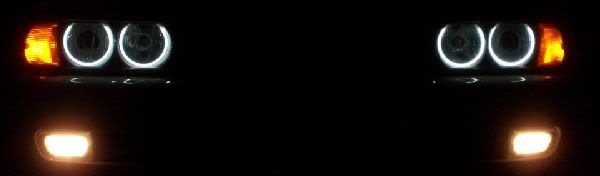
guys...i got this from umnitza...and i think they are much brigther than this
But any of this would give your car a BACK LIFT
kpeng needs to join bfc
have you seen the two compared? lul
hi i'm nickmanderfield.com and i hang out on the internets,
i also recently started to sell carbon fiber coasters.
Freude am Fahren
Mine arrived in today's mail. Haven't had a chance to install them yet.
chiefwej 2003 540i ///m-tech 6-speed Black Sapphire Metallic w/gray
See: My REGISTRY PICTURESMods:plate delete, debadged, 35% tint,euro console, Evans NPG (zero pressure cooling system), CDV delete, Rogue Octane SSK, RP Symcromax
Member
I have good news... I managed to add a resistor and the flicker is gone AND the error message is gone too!
Now I need to stress that this may be too early to tell if this is a good solution or not... but I will report back in a week if any problems happen.
Here is my thought process to what I did.... skip this next part if you dont understand electronics lol.... First I did some research to find out what other people have done to solve this problem. You need to understand that the reason the error code is being thrown is because the LED's do now draw very much current compared to a regular bulb. So I found that people were adding a resistor in parallel to the LED that is valued the exact same as the load of a regular bulb. Simulating a normal 5W light bulb means that you would need a resistor close to 40ohms(assuming 14volts operating). Using 40ohms would mean that the resistors power rating would need to be around 10watts to be safe and will probably need heatsinking and be huge in size, and blah blah blah.
The higher the power rating is on the resistor, the more expensive it will be to buy. I am cheap. I like cheaper alternatives. So I wanted to find out the least amount of current that needs to be drawn by the light to fool the error checking system. If I do that, then I can use a higher impedance resistor which will require a much lower power rating and will be a cheaper to buy.
I just happen to have a bunch of resistors laying around because I am a huge nerd... and in my collection of junk, I managed to find some 1 watt resistors that were 360ohms. 14volts going through 360ohms is only 1/2 a watt, so I am very safe with the power rating on the resistor. I tried just one resistor first but the codes still came. So then I put two in parallel to make a 180ohm load. GREAT SUCCESS!!! no flicker, no codes, and the resistors are only warm to the touch...
Pictured is my ghetto fabulous way of attaching the resistors. I just soldered them in a way so that I could still remove the LEDS if they die. I also did it like this so in the future if I decide to go back to the regular bulbs I can just easily cut off the resistor. Now I COULD have attached the resistor to the wiring harness that is attached to the car, but i didnt feel like cutting those wires and having to heatshrink the resistors.
Sooo.... less talk, more pictures......

my name is andy.
Awesome, thanks. I'll be going out to radioshack in the morning for some resistors.
Uh....I got nothing....
Got mine on Friday.
PM Sent.
Member
I would hold off on this as I have found another thread about a "NavCoder" that allows you to re-program the car so it does not check the bulb any more. I dont know if the re-programming will stop the flicker, but I would try this before adding resistors.
Uh....I got nothing....
Quack I am trying to send you a PM but your box if full. COuld you delete some of your messages.......please.
my name is andy.
I'd rather spend an hour throwing in a 10cent resistor than spend another $30+ on something so trivial.
ALPINE WEISS FTW
pm box deleted latif.... sorry man...
i did a whole e39 interior and license it was 12 with the puddle lamps, glove box, one in the trunk, 4 in the vanity mirror two in the rear pillars and the one in the center lamp....
Member
I would be building the interface box myself, so it would be cheap either way. Although, the resistor is definately the cheapest and fastest way to fix it! Just make sure the resistor ends doesnt touch the metal on the car. Definately do NOT try to insert the lamp assembly into the car with the LED's on so you wont short out anything.
resident, old fart
XBOMBER, GREAT solution. I hope it lasts. You obviously know your stuff, but as I'm sure you know the 360 ohms and the 14 Volts are not the necessary variables to determine the wattage necessary to dissipate the heat. The wattage necessary is a function of voltage and CURRENT flow. By effectively decreasing the total resistance of the lamp assm. by adding resistors in parallel, you have correctly increased the load (current draw) of the circuit making the LEDs "visible" to the LCM. Taking some current through the resistors also smooths the voltage flowing through the LEDs which will allow them to run cooler. You may have noticed some slight dimming of the LEDs as they run cooler. To determine the wattage resistors necessary to handle the load, you must know the total resistance of the new "circuit" (LED + resistors) and the voltage or the voltage drop x the current draw. My pure guess would be that 1 watt is not enough heat dissipating capacity, but if you say they are only warm to the touch, you are obviously 100% correct! Good job, buddy. Others must realize that these values may not work for every LED replacement. I don't believe Xbomber said it would. I think you guys are just trying to deal with this one issue and one brand LED. Obviously, a tail light assm with flicker like is going on elsewhere in this forum will not likely be cured with these values resistors and Xbomber never said they would. I just am cautioning folks who go from A to B to Z! There is virtually no risk here though of a fire or any other "the sky is falling" scenario. If the resistors get too hot, they will just go open and stop working. The downside is if you were to say put a 10 watt resistor in there that is too small a resistance value, you might increase the current draw TOO far thus causing the LCM to fail. I applaud Xbomber for coming up with a cheap and easy fix for this group buy of sorts. Way to go man!
BTW, your analogy is great and you essentially got to the right answer, but your rational is off a tad. To simulate a 5 watt bulb means you need to draw about 350 ma. @ 14 volts = 5WATTS Watts is a function of volts and amps-not resistance. So, the internal resistance of the 5 watt lamp conventional bulb is about 2.8 ohms 14/5=2.8 A 10 watt 14VDC lamp has an internal resistance of 1.4 ohms, etc. Again, your results are what counts, but watch the heat dissipation rating of those resistors. If the lamp is on continuous that is one issue. If it is a turn signal, the heat build-up will be less of course because of the duty cycle.
Last edited by m5hoot; 06-12-2009 at 09:15 AM.
Member
Maybe my numbers are off a tad because it did take me a few beers to get this done! You are completely right in the fact I did not factor in the load of the LED's into the eqaution.
My main concern in the end was for the resistors to only be warm. The last thing anyone needs is a trunk on fire!
...but after a week I am happy to report I still have no problems and no fires haha!
resident, old fart
ABSOLUTELY! I want the message that I conveyed to be this: Great work, you got the right answer you just used a different path, and the result is safe. Great work! That is the simple message- not the theory of ohms law.
I know how sometimes people will take one fix and then try to apply it to another completely different scenario. Therefore, if someone wants to figure it out for a different application, I gave the formula. In no way did I or do I mean to detract one smidgen from your work and your great solution. Bravo XBomber.
Uh....I got nothing....
My brain is now on fire!
Member
I totally understand where you are coming from. It is great to have a second set of eyes commenting on what I did so I can learn better for the next project. It has been about 6 years since I was in school for electronics, and I am amazed at how much stuff I have completely forgotten! I really appreciate your notes, especially commenting that this fix may not work with other brands of LED's.
resident, old fart
You still know your stuff, dude! Good job. I was just looking at a thread where a guy went LED on his turn signal bulb (don't ask me why he chose this spot) and of course it is blinking real fast because the load is too small. The vendor responded to buy his resistor kit. Wanna guess the values? 6 ohms at 50 watts! Now, this is for a 21 watt bulb if I recall correctly. Of course the wattage goes up as the resistance value goes down. 6 ohms is a small value, but makes sense because the internal resistance of the 3157 is probably about 1 ohm. This is why I was glad to hear you had good results with a much higher value resistance which drops the wattage immensely (Loveless, you're a trip). These resistors are $20 a pop! So, $40 for the privilege of an LED turn signal. Why.....
Member
I am very happy I was able get away with using a much higher value resistor. As for that guy adding a 6ohm resistor... that is ridiculous!
resident, old fart
The issue is: what load do you need to satisfy the LCM? In theory, a lamp is usually either an "open circuit" meaning the bulb is burnt out or a dead short meaning the wiring is bad. Anything in between could be assumed to be a functioning device. Obviously, use the least amount of resistance possible to satisfy the LCM. Remember, a 13 watt bulb at 13 VDC is a 1 ohm resistance, so 6 ohms is not unrealistic, but makes the sucker need to be huge. It likely acts just like a 3157 is there, but is that necessary to make the LCM happy? I'd guess it takes less load. Why would anyone go LED in the turn signal anyway. Speed to light is certainly not an issue. How much brighter can it be behind an amber lens? Seems like the least beneficial place to get a nice look. Just my .02 Not worth the hassle. If you all want to try a great look, replace the center lamp in the overhead console by the rearview mirror that comes on whenever you open a door. Great look and really functional.
Member
Just a correction on your calculations using the wrong Ohm's Law!
Back to basics:-
(i) Power in Watt (W) = Voltage (V) × Current (I)
(ii) Resistance (R) = Voltage (V) ÷ Current (I)
Therefore, Resistance R = V² ÷ W
or Power W = V² ÷ R
So, the internal resistance of a 5W bulb R=14×14÷5=39.2 ohms
and for a 10W bulb, its internal resistance is halved to 19.6 ohms.
 Posting Permissions


 Reply With Quote


Bookmarks