
 Member
I have waited a long time for this (too long) but my DIY turbo project is finally coming together. I was going to wait until the car was tuned so I could post dynos at the same time, but I figured why wait. For those of you who don't know the acronyms, RRT is Road Race Tech, a race shop in NoVA that specializes in building BMW race cars. TCD is Turbo Charging Dynamics, the source for most of my core turbo parts. First I want to give mad props to James at RRT. I turned my car over to him approx 70% complete. He did all of the fabrication, etc that I could not do in my garage. His attention to detail is impeccable. If you want any kind of work done to your BMW, FI or NA, and you are in the NoVA area, James @ RRT is your man. Next I wanted to give props to Todd at TCD. He helped me out a lot with turbo selection and other turbo info since I was a turbo noob when I started this project. I chose to go with TCD because I felt their core turbo parts were more DIY friendly, at least for me. Props also go to Cameron, aka highboostingm3 here on the forums. He was instrumental in providing me info and advice during the early stages of my research before I started this DIY turbo project. And lastly, Don, aka dcvee here on the forums. He gave me quite a bit of help and insight while the build was in progress since he had just successfully completed his E36 track turbo build.
But now to the car. Prior to FI, the car started life as 95 E36 M3 (with me as the original owner). It has gone through many changes over the years and just before the FI transformation, it was an OBD I S52 with just about every bolt-on you can think of. Before I went FI, I wanted more power via a standalone, so this is where I will start this story. I chose to go with the Haltech E11v2 for my ECU. I chose this unit for three reasons:
1. More than enough functionality to control the motor
2. Good balance between cost and performance when compared to other ECUs more commonly associated with BMWs (i.e. TEC3, AEM, Autronic, etc)
3. A good tuner, especially for FI, who is close to me (20 min from my house)
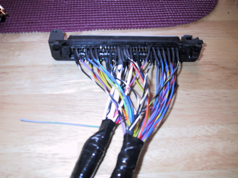
To keep wiring as "plug and play" as possible, I gutted an old stock E36 ECU to get access to the plug. I then soldered the Haltech supplied harness to the appropriate pins on the OEM plug:
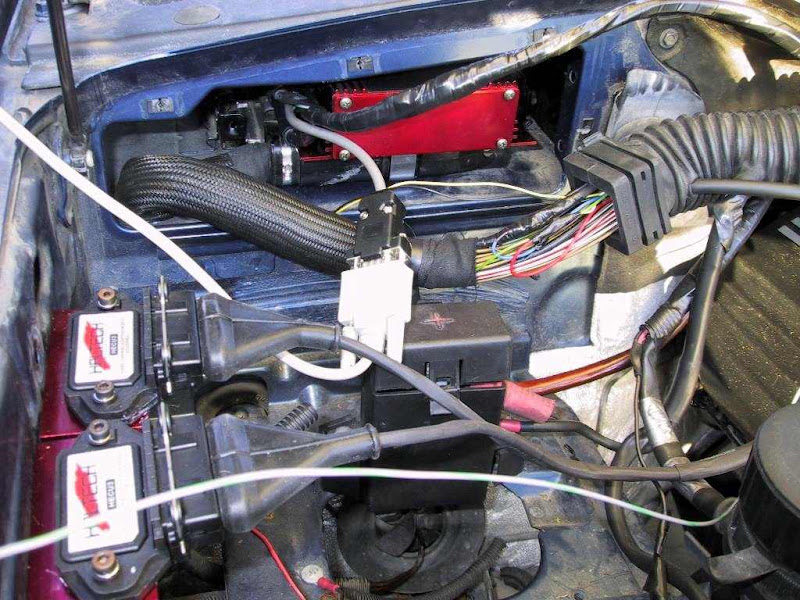
I then mounted the Haltech ECU on top of gutted stock ECU case.
The package fit nicely inside the stock ECU compartment.
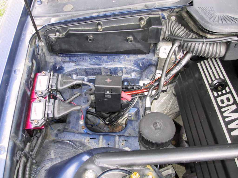
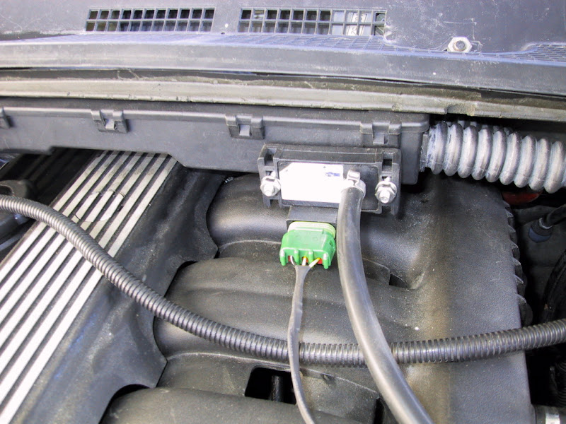
Unlike some ECUs, like OEM and TEC3 for example, the Haltech requires external igniters for the coils
I am using a standard GM 3 Bar map sensor for my setup. Since the HFM is gone, I rewired the HFM harness to use the map sensor via the stock ECU plug
Before I did the Haltech install, I installed the S/C on my E46 M3 (VFE Stage I) I soon realized that NA was not going to cut it for my E36 so FI was in its future. I was originally was going to do a S/C, but James at RRT convinced me that a turbo was the way to go for FI and the Haltech would give me a lot of flexibility and power potential when it was time for tuning. Thus the turbo project began. The car is approximately 90%+ complete now. James at RRT is finishing up some last minute details (did I mention that his attention to detail is impeccable?) before it goes to the tuner. Depending on the tuners schedule, my car could be done by the end of the month (or sooner hopefully). This also gives James more time to play around with my Haltech unit (initial setup stuff, etc), which is also mutually beneficial to me as well since he is familiar with other ECUs as well.
Below are some pics during various stages of the build. The engine bay has been tidied up a bit since some of these pics were taken. But the car is still in the shop now so I don't have updated pics yet. I will post up additional pics when I get them.
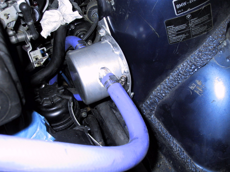
I removed the stock crank case vent system and went with an oil separator setup using the exhaust as my vacuum source. This unit is one I purchased from 034 Motorsports, which I mounted on the driver side shock tower using a very simple bracket. You can't see it, but there is a hose that drains any collected oil back to the sump via the stock "nipple" on the S52 dip stick tube. The check valve for the crank case evacuation system was installed in the downpipe.
To ensure there was enough fuel and no starvation issues, I did the dual fuel pump upgrade, replacing the main supply fuel pump with a Walbro unit. The transfer pump is just a stock pump. I didn't trust my stock FPR with over 113k miles on the clock so I replaced it with an Aeromotive unit. That small filter you see is for the fuel tank vent line that originally went to the charcoal canister.
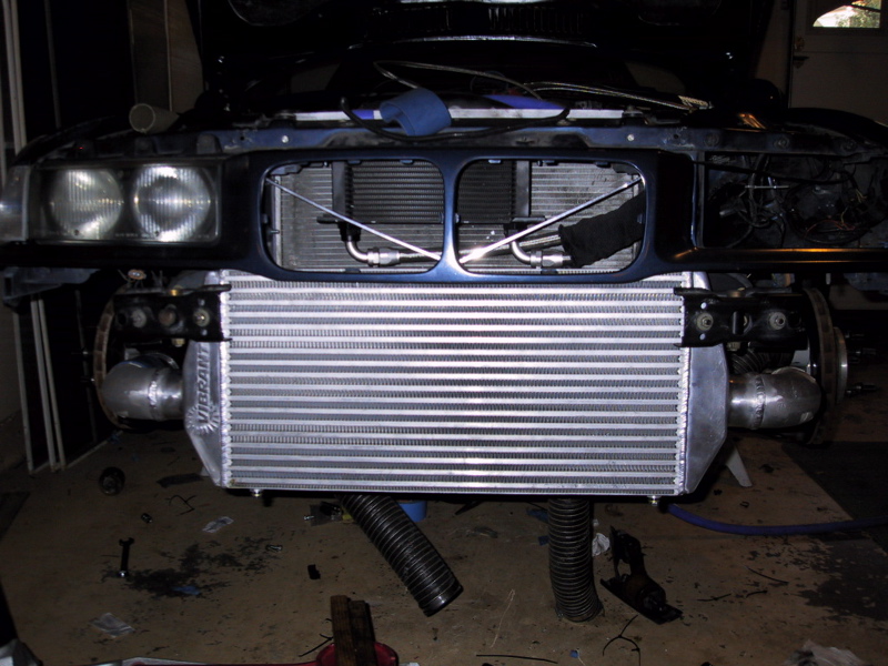
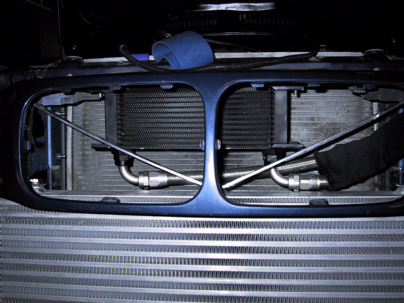
Next are pics of the intercooler and oil cooler. I ended up spending more that I wanted on the intercooler, but this was the only one I could find that was big enough to support track conditions, but still allowed for clearance of the brake ducts (the inlet/outlet are offset, unlike all other intercoolers I could find). Core size is 12"x35"x3.5". The oil cooler is part of the VPD oil cooler kit.
More pics and info to come.......
Last edited by jmciver; 10-11-2008 at 09:56 AM.
James
2005 Imola Red M3 - VF Stage I Supercharged Street/Track Car
E46 M3 VF Engineering Stage I Supercharger DIY
Light Fires N Burn Tires
Looks great!
Post up some more pictures of the piping and what not if you can.
Thanks!
Member
congrats on the build. James has done most of the work on my car that has been done at RRT, you're in good hands.
Member
Zip-Tie Engineer
OOOO This is my kind of build. Looking forward to more progress!
Member
Hey James, looking GREAT. And thanks for the shout-out. Anything else I can do, just ask!! You can't go wrong with RRT/TCD...that's for sure!!
This is going to be an excellent track car.
Don
Last edited by dcvee; 10-11-2008 at 08:10 AM.
MDORPHN
Didn't know that James worked on boosted BMWs
Neil
MDORPHN - 2011 Alpine White 1 Series M Coupe w/stuff
Y̝͎̘̍́ͣ̉͑̿̆Ō͎̼̺̬̒ͯ̃̇͗̂ U͈̖
RRT's work is amazing...
Member
Thanks for the kind words guys. I am kicking myself for not getting more pics of the tube routing with the bumper off, but I do have some that show the routing. For the most part though, I followed the standard routing path for E36 turbo builds. The one major difference being that I routed the outlet piping above the subframe, something that most E36 kits don't do. Which brings me to another brief topic, why DIY over a kit. For the most part, all of the kits on the market are designed as street kits first, track, if at all, second. After doing my research, looking at the available kits, and discussing things experienced FI builders and race car builders (including James at RRT), I figured out that no one kit on the market would completely meet my needs for my track turbo build. Not to mention the fact it was easier on the wallet to spread the cost over time and I enjoy most aspects of DIY. But now back to a few more pics and info.
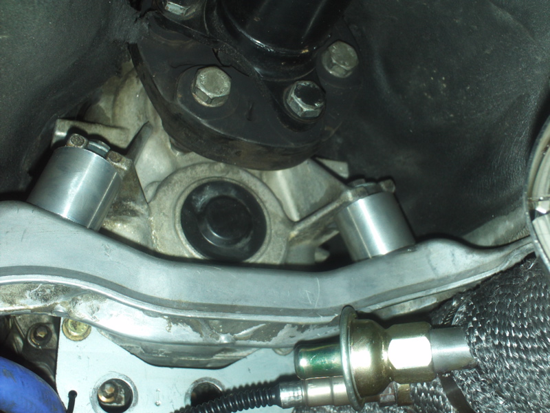
Below is a shot of the TCD engine bracket without the turbo installed. You can also see the VAC solid engine mount in this picture as well. My existing mounts needed to be replaced and the UUC race mounts I intended to use did not provide adequate clearance of the turbo. The turbo bracket is made of mild steel so I had it painted to prevent any corrosion issues.
To go with the solid engine mounts, I orignally was going to use a set of UUC race tranny mounts (very hard urethane). However, I found out it is not a good idea to use solid engine mounts with urethane tranny mounts, even the very stiff ones from UUC. So James very quickly fabbed some solid aluminum mounts (and I mean in like 15 minutes when I say quickly!!). Not pretty, but they get the job done.
Here is a shot of the turbo and oil drain. I originally wanted to go with (and purchased the parts for) an oil drain to the drain plug. My research told me that this method worked very well, especially for modest builds. Unfortunately, when I ran the car, including driving it on/off my trailer and into the shop, I had oil spitting out of the exhaust and around the turbo. After troubleshooting, it was determined that the oil was not draining enough from the turbo and the "choke point" was the 12x1.5mm to -8 AN adapter I was using. Also, my turbo, which is a full T4 turbo, does not use a restrictor for the oil inlet. This all means that a lot of oil goes in, but it could not get out, thus my oil issues. The problem was solved by James tapping the oil pan (something I definitely did not feel comfortable doing myself) and using some .625" ID hose (same stuff I used in my crankcase vent setup) and fittings.
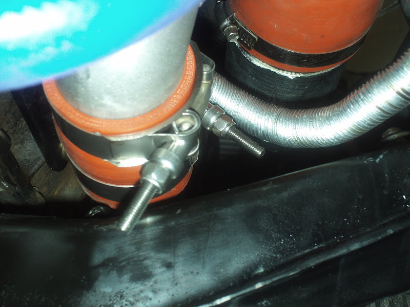
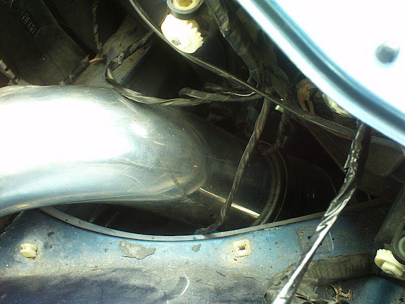
In this pic, and also the one above, you can see where I routed the intercooler piping above the subframe. The original TCD kit routes the piping below the subframe, but I did not want this for a track car. All I did was cut the turbo outlet and weld on an ebay 2" 90 degree cast aluminum elbow (actually, James @ RRT did the welding). The outlet piping stays 2" until the intercooler which made routing piping easier (and the fact that I don't have AC in the car).
This pic shows my filter in the passenger wheel well. It is actually pretty big and has a 3.5" inlet diameter. This is the filter I originally purchased for the car when it was NA. It is an Amsoil oilless filter, part of their Ea series. I was advised to use the biggest filter I could fit. Since I did not want to buy another filter, I decided to use this one. It is a tight fit, but it all clears. The hose to the left of the filter is the 2"-3" 90 degree silicone adapter to the intercooler.
Below are pics of the exhaust. I kept my original 3" in/out Magnaflow muffler and added a Magnaflow 3" in/out resonator to keep the car from being too loud. Unfortunately, I didn't realize just how much the turbo itself would muffle the car. As a result, the car was much quieter than expected when we started for the first time with the exhaust complete, yet it still produced a nice deep note. I can't wait to hear what it will sound like at WOT. James at RRT fabbed the exhaust, which was one of the last remaining jobs that I couldn't do myself. The piping is 3" aluminized steel. On the bottom pic you can see another shot of where the crankcase vent tubing connects to the TCD downpipe as well.
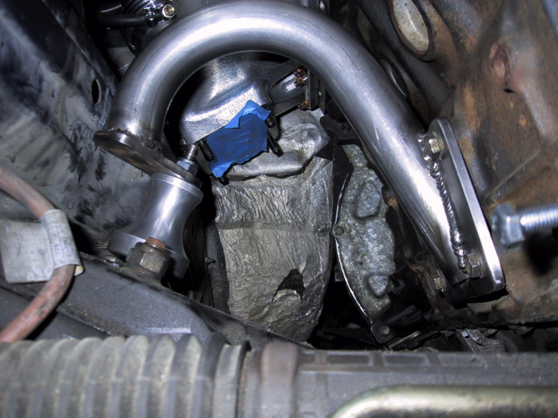
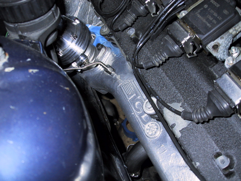
These next pics are shots of the manifold and wastegate. In the first pic you can also see where I had the manifold tapped for an EGT probe. The second pic shows where I cut the battery tray for better access to the wastegate.
To help with heat, the manifold and turbo exhaust housing are all ceramic coated. After hearing stories of the heat causing potential transmission issues, I wrapped the downpipe as well. The orange couplers are high temp silicone couplers from boostcontroller.com, another precaution against the heat. I also wrapped the intake and outlet piping with heat reflective material in the areas next to the block.
Thats all for now. I should have better engine bay pics on Monday
Last edited by jmciver; 10-11-2008 at 05:37 PM.
James
2005 Imola Red M3 - VF Stage I Supercharged Street/Track Car
E46 M3 VF Engineering Stage I Supercharger DIY
Member
Dang i like the details. BTW, you wouldn't to have a vid of the exhaust bc I'm about to do the same setup w/ Magnaflow muffler and resonator.
Member
Not yet. When the car is on the dyno getting tuned I will try to get some vids. But as I said before, I expect it to be pretty tame as far as loudness is concerned if the exhaust note at idle is any indication.Originally Posted by BadBoostedBmwM3

James
2005 Imola Red M3 - VF Stage I Supercharged Street/Track Car
E46 M3 VF Engineering Stage I Supercharger DIY
License Revoked
Very nice work James. I like the build.
Member
Thats what i want= sleeper.
Member
+1
Nice work on the wrinkle black valve cover, i did the same thing the other day when i just finished rebuilding the top end of my m50.
I especially love the fact that you are piping everything about the subframe, can you see any piping sticking out at all when the car is sitting on the ground?
Member
If you are talking about under the car, the answer is no. However, you can still see some of the intercooler piping through the brake duct openings.
James
2005 Imola Red M3 - VF Stage I Supercharged Street/Track Car
E46 M3 VF Engineering Stage I Supercharger DIY
Member
post more pics please!!! and what size turbo did you end up going with?
also how much power are you hoping to make?
Member
Ok, I went by RRT today to do a little "tweaking" on the ECU so that the car is more drivable and stable before it goes to the tuner. I did this when I first installed the ECU with 24# injectors and was able to get the car very drivable and idling properly. Unfortunately, a misfire problem that I thought would disappear when James finished his fabrication would not allow me to properly tune the car. Under the watchful eye of James, I was able to troubleshoot the problem down to one of the ignighters causing the misfire in one of the cylinders. Luckily, the Haltech ignighters are just OEM parts made by Bosch so James should be able to get one tomorrow and swap it in. Once that is done, between James and myself we should be able to get the ECU stable before it goes to the tuner.
As far as turbo specifics and power goals are concerned, I got the turbo from TCD since it is the best fit with their hardware. The turbo is a T4, specifically a T04e-60 w/S5 turbine and .58 housing. My power goals are a modest 350-400 whp all on stock internals. However between the size of the turbo and the flexibility of the Haltech, my setup is probably capable of much more. Only time will tell.
But now on to a few extra pics......
Here are some shots with the bumper on the car. Although the in/out sides of the intercooler are visible through the brake ducts, I still was able to retain my brake ducting to the rotors. It is still better than having no ducting at all.
Here are some shots of the BOV section of intercooler piping
In this pic you can see the crank case vent hose connected to the crank case. James at RRT made a special fitting for this. You can also see the -4 AN line coming out of the VPD oil cooler cap. And you can also see a shot of the Bosch "Green Giants" 42# injectors. I went with the Green Giants on the recommendation from James. They use these injectors in their race cars due to their conical spray pattern. Also, that is an S52 fuel rail which made installation of the Aeromotive FPR easier.
Next are some shots of the turbo inlet/outlet piping from the top.
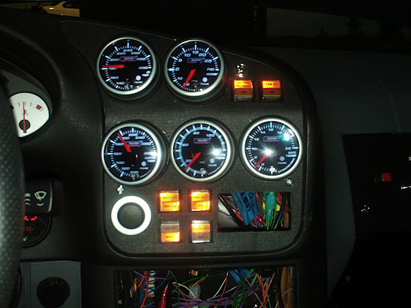
Here go a few interior shots. The left vent was replaced with the LC-1 Wideband O2 Sensor and battery shut off switch. In the center console area I added gauges for Oil Pressure, Water Temp, Oil Temp, Boost/Vac, and EGT and also switches for the engine start (it is a Z8 start button), main ignition power, electric engine fan, map selection (the Haltech has 2 user selectable maps), datalog actuation, defogger and one other switch I have not assigned yet (it is currently labeled for meth injection. In the last pic I got rid of the glove box and made my own panel out of PVC plastic. I ultimately plan to mount a small PC behind it that will be connected to the Haltech full time.

I guess that is all for now.
James
2005 Imola Red M3 - VF Stage I Supercharged Street/Track Car
E46 M3 VF Engineering Stage I Supercharger DIY
Member
the pics look great..very nice car..i hope you get her running right soon and then get her on the dyno..
Member
great pics! great build
A few questions though.
Where did you get your intercooler mount from?
Do you have to run your crankcase vent into the exhaust?
Do you think your oil drain will drain in high G force areas of a track?
And Do you have any pics of thoes gauges luminated?
Member
Very nice James!!! It won't be long now.....hehhe.
Don
Member
Thanks!
I got the intercooler bracket design from another forum member. I can't remember his name, but he posted his design on the forums (I attached it to this post as well). My bracket is a slight variation of this design. I chose to vent the crank case via the exhaust based on the recommendation from James @ RRT. They use this method on their race cars and is a very effective method to evacuate the crank case. The oil drain is pretty big at 5/8" so I think it should do the trick, but only time will tell. No pics of the gauges illuminated yet. I will see if I can get some soon.
Last edited by jmciver; 10-13-2008 at 10:46 PM.
James
2005 Imola Red M3 - VF Stage I Supercharged Street/Track Car
E46 M3 VF Engineering Stage I Supercharger DIY
Member
I had a request to see my gauges illuminated. Here is a shot below.....
On a different note, I have been chasing down a misfire the past few days. It ultimately turned out to be not one, but both of my igniters for the coils (I used 2 3-channel igniters) failed. Not only did they fail, but they both failed on the same internal channel, causing the misfire to either be on #1 or #4 or both. Go figure
........ Anyway, I should have two good igniters in the car tomorrow and all should be well
.
On a good note, since the misfire was intermittent, I was still able to do a bit of no load tuning using the "quicktune" feature of the Haltech. The car idles pretty well now and is more drivable. Hopefully the car will be ready for the tuner in about a week or so now that I have solved the misfire problem.
James
2005 Imola Red M3 - VF Stage I Supercharged Street/Track Car
E46 M3 VF Engineering Stage I Supercharger DIY
Someday...
This build is SWEET! I love that you're so hands-on and how methodically you go about it. Props to you!!
-Ted
License Revoked
I dig the gauges. What are the switches for?
Member
In the very top, the left switch is for the stock blower for the defroster (in case the windows get fogged up due to rain, etc), with the silver switch right above it being the blower speed selector. The one next to it is the data log on/off switch for the Haltech.
In the bottom set of switches, the top left is the ignition switch. When the battery switch is on, the top half lights up, then pressing the switch turns on the ignition, etc. The bottom left switch is the Map selector switch. The top right is the engine fan override switch. And the bottom right is the meth injection switch. I don't have a meth injection system, nor am I sure I will get one. That switch has a relay connected to it so I can control whatever I want in the future (cool suit maybe
James
2005 Imola Red M3 - VF Stage I Supercharged Street/Track Car
E46 M3 VF Engineering Stage I Supercharger DIY
 Posting Permissions


 Reply With Quote


Bookmarks