
 Member
For some reason, I was like, hmm, what if something doesn't work out and I have to put it back together as it wasOriginally Posted by 2kredz3

.
SOLD MAY '14
Mods: 6psi Supercharger kit; Rogue RSM's; DINAN strut brace; Magnaflow exhaust; Stewart waterpump; Stoneguards, Glove box fix, M Shift knob; Aux input adapter; Mesh bumper grill; Projector Z II headlights (35W Xenon), IE alu radiator, ARD wheel studs, H&R coilovers, Work VS-XX wheels/Hankook V12 tires, VANOS fix
Supporting Vendor
it doesnt mess the pad that bad.
Member
I compress the caliper before I loosen the guide pins....using a 6" C clamp. You can swap pads without ever letting go of the caliper.
Craig BricknerClick to Join: BMWCCA # 366493
BMW CCA/PBOC/Chin Motorsports DE Instructor
2008 M3 Sedan Jerez/Black
Member
Any help is appreciated.
Member
Member
http://forums.bimmerforums.com/forum...d.php?t=961644
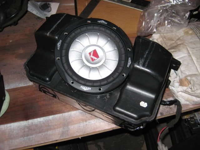
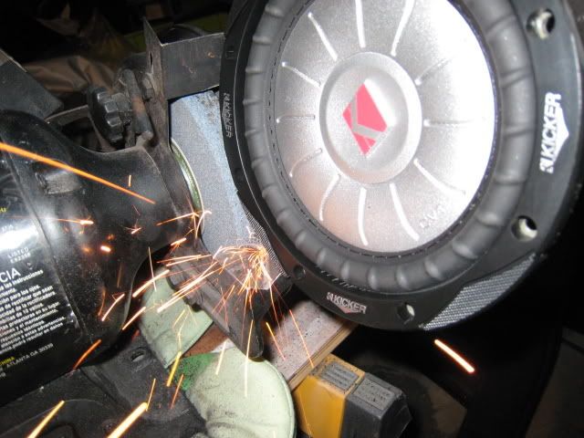
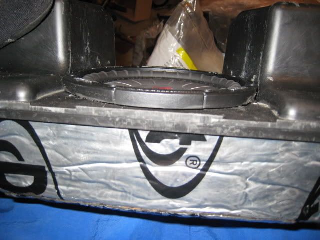
I was considering getting Beyma Power W6 sub but its depth seemed a tad too deep. The kicker CVT65 didn't require as much depth but the overall diameter was too wide for our enclosure. I grinded the edge of the speaker to make it fit. I also remove the cosmetic rubber piece that goes around the magnet for extra clearence.
Kicker CVT65
Peak watt 300
RMS 150
Frequency 25-350 Hz
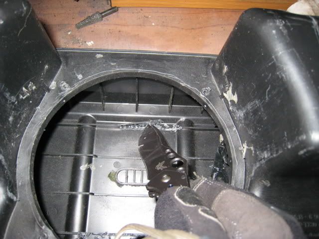
The bulges on the enclosure get in the way.
I grinded out the plastic then went into metal little bit
My dremel broke so I used a knife to remove some of the plastic for extra clearance. I did this before I realized that you could remove the rubber base around the sub magnet. You might not need to cut as much if you just remove the rubber base.
[/
Last edited by Z-Thrizzle; 06-04-2010 at 10:04 AM.
-Phil
I should get back to work
I know, I know, there are many fogged airbox DIYs around the web. I did it a little bit different though and was quite happy with the results.
In short:
I have a 1.9 '96 with 107k on the clock and what I wanted to do is not mess with the original intake, so that if I'd screw up, I could just refill the hole and not do any extensive damage.
Also, I understand that the biggest problem with the original intake is not the temperature of the air, but the diameter of the intake (not enough air volume coming in).
I drilled a second hole in the airbox and conected it with a duct to the side of the radiator, opposite of the original intake. This way I don't have to worry about crap or water getting into the airbox, which was a worry of mine since in rainy season, some streets here turn into white-water rivers.
Orange arrow is original intake, green arrow will be the new second intake.
This DIY is for dummies, as you will see by the photos. A lot of DIYs i read had photos that did not make any sense to me as there was no reference or anything. I hope I did a better job at that so now everybody and their pet gold fish can do this "mod".
If you would like higher res photos, PM me and I'll send them to you no problem. I went with very small photos to not take up too much space.
What you need:
Ok, since I'm a foreigner, I don't know if I've gotten all these names right, but here goes. From any hardware store:
Basically, if you have none of the above, it guess it should cost you less than $40.
- 3 inch duct (you really need just like 6 inches)
- 3 inch duct connector
- 3 inch duct clamp
- 2 1/2 inch bit for your drilling machine (to cut circular holes)
- some isolant (I used isolating tape)
- Silicone (maybe some glues will do even better)
- your regular kitchen scissors
- some sandpaper (i used 60 and 220)
Here is a pic to show most of the products I bought:
Does it work:
If you didn't fog your airbox yet, do it! You won't regret it one big. I have no dyno maps to prove anything, but my engine now produces a deeper sound and I feel there is more umpf, which I think is worth waaay more than the time and money I spent on the project.
Time and skill:
I did it in about 1 hour total; 40 minutes to prep the airbox and 20 minutes fitting the hose and box back in. I'm a complete noob at any car DIY projects and have a tendency to break or fumble everything I get in my hands. If I can do it, you can.
Step 1, preparing the airbox:
Pop the hood and locate the aribox using the picture below as reference. Now take out the airbox by loosening the clamps (red arrows), taking out the air sensor (orange arrow) and unscrewing the two bolts that hold the box into place (green arrows).
Now, with the airbox disconected, take it some place you can easily work. I did it in the kitchen.
Grab your drill with the 2 1/2 inch bit and drill a hole just like in the next picture. If you want, you can drill a bigger or smaller hole, it's up to you.
Now cut the plastic harness that's inside the airbox, so your duct conector can fit inside, and sand the circle cut you just made so that later on the glue or silicone will attach better. Also, now's the time to clean the airbox.
Picture of the harness bit I cut out:
Step 2: fitting the duct conector
Now my hole was 2 1/2 inch and the duct 3 inch. Trust me, I wanted a 2 1/2 inch duct, but couldent find one. So what I did was just adapting the conector, shaping it like a cone so at one end it would fit my 2 1/2 inch hole, and on the other the 3 inch duct.
I made little cuts in the smaller end of the conector and bended them back so they would prevent the conector from slipping out of the airbox. You can cut the duct and the conector easily with regular scissors, but be wary of the razor sharp edges it leaves. It gave me various little cuts on my fingers.
Now, get the conector in the airbox, fold the ends you cut backwards and start loading the seams up with silicone. There probably are better adhesives to use, but I'm no expert and silicone makes sense since it dampens the vibrations of your car, instead of solid glues which might break over time.
A (pretty bad) picture of how the inside of your airbox now looks:
Pretty DIY right?
On the outside of the box, I put some masking tape on the conector. Don't ask me why, I just felt like it. In the next picture you can see how the conector is "coned" a bit (going from a 2 1/2 inch diameter to 3 inch). What the picture doesn't show is that I loaded the outside up with silicone as well, but that was after I took the picture.
Now, after all the adhesives are dry (next day), you have to trim the part of the cone on the outside a bit, because you don't have much space under the hood to conect the duct and get the duct to bend to the left (don't have a picture). I left about an inch of conector sticking out of the airbox, but you can go as small as your duct clamp is wide I guess.
Step 3: fitting the damn thing
Since they make you buy 3 feet of the duct and you only need about 6 inches, you can afford to do trial and error with fitting the duct. Cut about 7 inches off the duct, leaving clean cuts, and rout it like the green arrow on the next pic. The duct's great advantage is its flexibility, you can pretty much mold it into any shape and curve. When fitting the duct, notice how it is like a harmonica, it folds in and out easily. Make sure you leave the ends folded, so that later when you fit the airbox, you can fit it easily and then fold the duct over the conector.
On the front of the car, the duct will be visible like so:
When it all fits right, take the duct out, wrap it in the insulating tape where the duct hits the cooling resevoir, put it back in, slide the clamp on and bring in the airbox (here is where you might need more than one try). Attach the airbox with the two bolts to the frame, slide the duct over the conector and tighten the clamp.
Now what you want to do is get a screwdriver or something long and thin to get it inside the duct and push the walls of the duct outwards, to open it up: you want as much air to flow through as you can.
Also, make sure the intake opening (last picture) is as wide as you can get, so it captures the maximum amount of air.
Here is how it looks all assembled, note the amount of insulating tape I used:
That's all folks!
Please let me know what you guys think of my first write-up, critisism and worshipments alike. As I said, I'm very pleased with the result and the litte amount of time it took me. I probably spent more time doing this write-up, but I guess it was about time I contributed something to this great board instead of just asking the guru's in here.
Last edited by mabakker; 07-20-2009 at 07:31 PM.
Member
Member
Awesome write-up! I used your stereo DIY as well. Both absolutely excellent
Member
Procedure to Reset Window regulator - POST #8
http://forums.bimmerforums.com/forum....php?t=1366261
DO IT YOURSELF.
Here is a guide for performing the shift pin service on your manual transmission:
How to: Service your transmission shift pins.
Member
BMW CCA Member
Excellent write-up! Thanks Derek!
Member
################################################## ###############################
HOW TO: BMW Z3 3rd BRAKE LIGHT GASKET REPLACEMENT
################################################## ###############################
A common complaint with leaks on the BMW Z3 seems to be in the boot and specifically around the third brake light - the root cause for this is because the gasket perishes over time.. it's a fairly cheap and straight forward process - but I couldn't find any guides for it so thought I'd throw one together as I've just done mine.
Tools/Parts needed:
1 x BMW replacement gasket (p/n: 63 25 8 389 735)
1 x small flat blade screwdriver
1 x medium Phillips head screwdriver
1 x T-8 precision screwdriver
1 x cloth/rag
Step 1:
Open boot and remove black plastic protective cover - this just prise away from the body work (pull it gently):
Step 2:
The PCB which powers the individual brake lights is held in place by 3 x Phillips screws -take your Phillips screwdriver and remove these (highlighted in green circles in below pictures to show location):
Step 3:
Next you need to remove the 2 x T-8 screws which hold the black plastic back plate to the front red plastic lens - these are located either side of the black plastic back plate:
All fixings should now be removed (3 x Phillips screws and 2 x T-8 screws):
All that is now holding the front lens and black plastic back plate in place are the 4 black plastic compression clips - these are located here:
All you do now is work from one side to the other pressing them (gently!) together - once you release the last clip - the front red lens and the back black plastic piece separate:
Step 4:
Remove the old gasket from the red plastic lens and replace with the new gasket:
Comparison shot of old gasket (left) and new gasket (right):
Step 5:
Take your cloth/rag and clean the area around the third brake light to make sure it is free from dirt and grime and to ensure that it's dry:
Final Steps:
Refitting is now just a reversal of removal - this can be quite fiddly though! - although once you have the red lens and black plastic backing clipped together its a fairly easy. The reason I suggested a small flat blade screwdriver above is because this will help enormously when it comes to clipping the black plastic clips onto the PCB.
Job done (and no more leaky boot!!
Hope this helps!!
Link to original thread: http://forums.bimmerforums.com/forum....php?t=1403850
################################################## ###############################
HOW TO: BMW Z3 CHANGE STOCK ORANGE INDICATORS TO CLEAR
################################################## ###############################
Front:
http://forums.bimmerforums.com/forum....php?t=1285943
Rear:
http://forums.bimmerforums.com/forum....php?t=1285961
HTH
Last edited by pangsterZ3; 02-22-2010 at 04:16 PM. Reason: Automerged Doublepost
2016 BMW M135i LCI (F20) = Current
2016 Mercedes Benz GLA 200 AMG Line = Current
Member
Don't shoot me as I know this write up doesn't concern a BMW as I did it on my C70 - but its a common affliction for most cars with leather interiors so i thought it might help!
I finally got round to sorting my interior out - so thought I'd do a quick write up.
I ordered my Liquid Leather Scuff Master treatment kit from http://www.liquidleather.com - in the order form or if you call you specify the make, model and year of car as well as colour of leather. They then send you out the kit pre-mixed to a sample they hold on file. If you have any reservations about colour matching then you can always send them a small sample of your leather and they'll match it for you - although in the kit you do get 2 small bottles of toners to make up for any slight variations.
Here's a picture of what you get in the kit as well as some other items you might find useful for this job:
Kit contents:
GT12 Liquid Leather Cleaner
GT11 Liquid Leather Conditioner
Scuff Master Touch Up Kit (contains 1 x bottle of premixed dye, 1 x light toner, 1 x dark toner, 1 x gloss enhancer and 2 x sponge applicators)
In addition to the supplied kit you might also want to consider the following:
Rubber/latex gloves (if it can dye leather I'm pretty sure it can dye skin! lol!!)
Small artist paintbrush or cocktail stick (for application of neat dye)
Cotton cloths/rags
Methylated spirits
Small plastic bowl
Step 1:
Hoover your interior and seats
Step 2:
Clean all of your leather interior thoroughly with the supplied GT12 Liquid Leather Cleaner. You can use a small nail brush or old toothbrush to agitate the cleaner on stubborn areas and then make sure you clean off all the residue and leave to dry.
Step 3:
Once dry - wipe down the seats/interior with a mild solvent like methylated spirits and dry.
Step 4:
Take your pre mixed Scuff Master dye and apply neat to a small crack/scuff with your cocktail stick/brush and wait for it to dry. Once dry inspect to see how accurate colour match is and add toner to adjust accordingly. Once you are happy with the colour match proceed to paint in the remaining cracks - I found that this worked best by working along the creases and not try to over paint areas that shouldn't have dye applied. The same applies to scuffs - apply a slightly diluted mix (10-20% water) to the scuffs with the sponge applicator.
Step 5:
Leave the dye to dry for around 1 minute then wipe off with a damp cloth (work along the direction of the cracks/scuff) and repeat Step 4 if necessary. Once you are happy all of the scuffs/cracks have been dyed then move onto Step 6.
Step 6:
Prepare a colour wash for the treated seat - for my first colour wash I mixed around 80% dye with 20% water and applied this over the seat. Again I let this dry and then rubbed down with a damp cloth. I was quite happy with the match/balance of the colour at this stage so mixed my final colour wash which consisted of around 20% dye and 80% water and added a little drop of the gloss enhancer I received with the kit. This colour wash was then applied to the seat and I left it to dry (24 hours).
Step 7:
Take the GT11 Leather Conditioner and work this into your leather until it is completely absorbed. The aim here is to apply an even coat and make sure you work the conditioner completely into the leather. Areas which are particularly dry may require repeated application - just be patient and make sure it is worked in properly.
Step 8:
Job done!
EDIT: Pictures of my E36 Compact seats before and after treating with Liquid Leather:

Last edited by pangsterZ3; 07-26-2010 at 10:14 AM.
2016 BMW M135i LCI (F20) = Current
2016 Mercedes Benz GLA 200 AMG Line = Current
Member
New to this so I am not sure if I am at the right place to ask a question...
I just got my first BMW. A 1996 Z3 In mint condition with 78,000 miles. It was pre wired for keyless entry/security system but did not come with it. I bought one on ebay that came out of a 1997 Z3. I can't get it to work. Does it have to be programmed into my car by the dealership? It will only make a three beep noise no matter what button you push and doesn't lock nor unlock the doors. The siren was put in no problem as was the led light etc. Everything seems to be in order but it's not working..
Thanks
Member
Three (3) beeps indicate that a door, trunklid, hood, or radio switch isn't satisfied (closed).
If you're getting that far, it's probably hooked up correctly.
You'll find out how to troubleshoot the individual switches with a search on this forum.
In the future, after you've tried searching for an answer to your question, you should post in the open Z3 thread, as it's more likely to be seen/read. This thread is for how to do it write ups
Welcome!
Member
TOOLS/EQUIPMENT NEEDED:
* Sharp knife and cutting board
* TomTom/Sat nav sucker (makes removing the gauge binnacle a doddle)
* Soldering iron (with fine nib) and solder
* Dremel / drill or cutting tool i.e stanley knife etc
* Belt hole punch
* UHT spray glue or thin double sided tape or similar
* Small screwdriver
* Torx screwdriver (or whatever screws hold your gauge cluster in usually a T20 or a T25, but some have phillips!)
* Precision Torx screwdrivers (T10, T8 and T6 are useful)
* Table cloth/soft cloth
* Crimper and crimps/scotch locks or t-tap connectors
* Insulating tape
* Ruler/measuring tape
* Clear plastic and CD pen or tracing paper and pencil
* Fork
* Cable ties (optional)
* Thin nose pliers
* 9v square 2 pin battery (for testing purposes)
* 5"x6" EL panels (x2) and 12v transformer
* Dials of your choice (I used Lockwood, you could use any dials including stock)
* Y lead to run 2 EL panels from 1 invertor
* Dial paint or pen (optional)
STEP 1: Removing the gauge cluster from your car:
This guide assumes you know how to remove your dials from your car - there's plenty of guides on this on the net so I didn't see the point into going into this step in any detail, but I've given a brief description below.
In essence you take your T20/T25 screwdriver (there seems to be a variance in screws used across the models!) and unscrew the 2 screws holding your clocks in place (highlighted in green on the below photo):
N.B. If you have a compact or Z3 this can be achieved with a careful bit of maneuvering without removing the steering wheel! - Once both screws have been removed, draw the dash forward (you might find your sat nav sucker comes in useful here!).
Once the dash has been drawn forward - have a look round the back and you will see 3 multi plugs (white, blue and black). These all have lock levers which hold them in place and can be simply unlocked by pressing gently down on the retainer tab with your small screwdriver and the sliding the lever upwards.
STEP 2: Separating the gauge cluster:
You should now have the gauge cluster removed from the car. Spread your cloth out on your work surface and place the cluster face down (clear plastic on the cloth). The reason you're using the cloth is to make sure you don't scratch the face!
There are 5 torx screws that hold the back of the cluster onto the clear window and black plastic section. Unfortunately the picture I took at the time came out a little blurry!! - so I've tried to show the locations in red on this picture below:
Take your T10 screwdriver and remove all 5 screws (the 2 in the corners and the 3 in the centre). You should now be able to separate the blue back cover from the rest of the cluster.
There are now 3 thumb screws which clamps the black plastic surround to the dials (these are shown below in red):
Turn these through 180 degrees (I found using thin nose pliers helped enormously here!) and the front part (clear plastic screen and black plastic surround) will come away from the dials.
You should now have something that looks similar to this:
STEP 3: Removing dials and needles:
This step could vary depending on the dials you're fitting. In my case I decided to remove the stock dial face. To do this, you first need to remove the needles. BEFORE removing the needles it is strongly advisable to make a note of their exact position. To do this you need to remove the stop pegs for the speedo and rev counter (your think nose pliers will come in handy here). You'll notice that both needles drop down slightly - it is this starting position you want to take note of! I simply measured from the tip of the needles to static parts of the cluster (i.e. screws etc).
Once you're happy you've noted all of the needles current positions you can go ahead and remove them. I took my fork and using the middle 2 prongs, slid it gently under the base of the needle (ensuring I was applying the same pressure across it's base) and then gently prise the needles up. It's important you don't force them as this could bend/damage them. There will be a slight resistance but you should be fine as long as you apply pressure evenly.
Once all the needles are removed you can then remove the gauge face (this is just stuck down onto the clear plastic backing with a little adhesive and should just lift straight off).
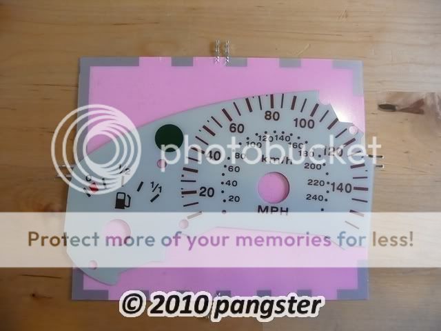
STEP 4: Preparing your new dials (EL template):
I guess this is when the arty/craft part of the project begins! My Lockwood dials came in 2 separate halves which made this slightly easier as I was working with 2 x EL panels (1 for each side).
Take your new dial and offer it up to your EL panel:
You need to decide the best position for this. Bear in mind that when you're cutting round the EL panel you need to leave yourself a pair of connectors to connect to!! i.e. do not place the gauge in the middle of the panel and cut round it! NB where you also see the silver strips on the edge of the panel, these are non light emitting so also bear this in mind!
I position min at approximately 45 degrees on the panel which meant that I had 2 connectors coming out from the top (round about th 100 mph mark) as can be seen here:
You'll also note from the above that I have a silver strip in the bottom left hand corner (this is fine as well as there is nothing that needs to be illuminated here).
STEP 5: Finishing off your EL dials:
You now have a rough template for your EL backing for your dials. You now need to ensure that all of the holes and windows required to let light pass through from the back or to allow the needles to be fitted are cut out.
To achieve this I placed the dial face on my EL template and took my belt hole punch (selected the appropriate size hole and punched the EL template). For the larger holes for the needles - I placed the dial face and EL template on my cutting mat and cut slowly with a very sharp craft knife - your EL template backing should now look something like this:
You still need to cut out the windows for your indicator and for the fuel tank/temp (depending on which side you're doing) - I found the best way for this was to place the dial under a clear piece of plastic and trace round these areas (tracing paper would work equally as well):
I then transferred these onto the EL backing template and cut them out (TIP: you can use the bigger hole for the needle (speedo or rev counter) as a circle template for your indicator to ensure you get a perfectly smooth and round circle (they're the same size) - you should now be left with this:
It might be a good idea at this stage to check how they'll actually look (to make sure you're happy with them and make any final tweaks) - to do this just hook up your 9v battery to the transformer and connect to the EL backing terminals:
Once you're happy with the results, you now take your glue or double sided tape (I used UHT mounting spray glue) and glue the dial face to the back EL panel (apply some pressure to ensure you get the dial and panel as flat as possible.
Now repeat the above steps for the other side!
STEP 6: Soldering the leads/tails to your EL dial terminals:
You now need to solder the leads that run from your EL dials to your harness/12v transformer. Take your soldering iron and solder, tin the wires for the tails and then solder onto your terminals on the EL panels:
STEP 7: Installing EL dials onto cluster:
Offer your new EL dials up to your clear plastic panel/backing - make sure you're happy with the fit/position and plan how you're going to run the wires from the EL terminals.
Apply a little adhesive to the back of the EL panel and position on the clear plastic panel. Install your needles (making sure you position them based on the notes/measurements you took earlier):
Now you need to take the clear plastic window/black surround and re-attach it to your cluster - this is the same as detailed in the removal step before where you offer both parts up and the twist the 3 thumb screws through 180 degrees:
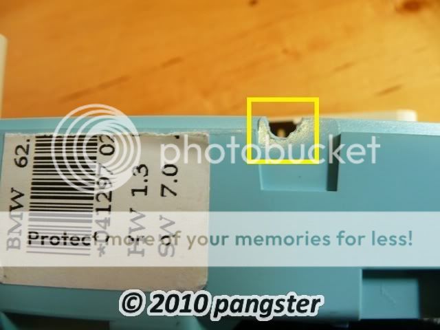
Flip the cluster over onto it's face and again place down on the towel/cloth to ensure you don't scratch the clear plastic. You should now see your 2 leads running from your EL panels. You need to decide the best way to route these. In my case I had one coming out the top and one coming out of the bottom (highlighted in yellow below):
Based on where your terminals are and how you intend running your leads will decide where you need to modify the rear blue plastic cover. I took my Dremel and made a small incision in the top for my first lead and then made a slight groove in the bottom for my second lead (shown in yellow below):
You now need to feed your wires through the cuts/grooves you've made and then screw the unit back together again (5 x torx screws):
And then take both leads and connect to your Y lead which will allow you to run both panels from 1 x 12v transformer:
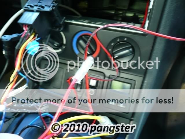
STEP 8: Installing EL dials/cluster into your car:
You only have 2 wires you need to fit in order to install your dials. You need a ground and a switched live. I decided given the location of the cluster that the best source for both of these would be from the stereo harness. The reason for this is that it gives you a few choices as to where you want to tap in for the switched live. I was lucky enough to have an Alpine stereo fitted which came with a spare switched live lead (so I justed needed a bullet connector) but I also contemplated tapping into the illumination wire instead so that it came on with the headlights and could be adjusted. I chose the spare switched live because I'm lazy! LOL!
If you want to use your stereo harness then the first step is to remove your stereo and then feed the wires through from the cluster to the opening for your stereo:
You can see from the last photo above that I had already tapped in to the ground with a scotch lock. In hindsight I would have used t-tap connectors to do this but had none to hand!!
I then identified which switched live source I was going to use (as mentioned before my headunit came with a spare one):
Which meant all I needed to do was add a bullet connector to the live from the 12v transformer and connect it and that completed the wiring:
You now need to feed all the wires back behind the dash. I used cable ties at this point to tidy it up a bit.
Refit your stereo.
Now plug the 3 multi plug connectors back into your gauge cluster (black, blue and white) and make sure they're secure. It might be a good idea at this point to check to make sure everything is working. Once you're happy that everything is fine - go ahead and refit the gauge cluster back into the dash with the 2 screws removed before.
STEP 9: The end result:
You should have something that looks like this:
Quick video of them in action and to show the colour match with the rest of the interior and stereo:
[ame]http://www.youtube.com/watch?v=59Dh_-1NDqI[/ame]
Last edited by pangsterZ3; 10-16-2010 at 09:12 AM.
2016 BMW M135i LCI (F20) = Current
2016 Mercedes Benz GLA 200 AMG Line = Current
Milk was a bad choice...
Those dials are badass. I'll be doing this soon, thanks!
Member
COMPARISON OF STOCK Vs CUSTOM EL DIALS:
EDIT: I thought a quick video would show the dials better than pictures! (plus I wanted an excuse to use iMovie! LOL!):
[ame]http://www.youtube.com/watch?v=3_ADTC93u4M[/ame]
Last edited by pangsterZ3; 10-13-2010 at 02:55 PM. Reason: added link to short video clip
2016 BMW M135i LCI (F20) = Current
2016 Mercedes Benz GLA 200 AMG Line = Current
Trend-Setter
http://forums.bimmerforums.com/forum....php?t=1178493
did this to my ///M5, will be doing it to the Coupe once it cools down this winter.
Member
Can someone post the link to this DIY project? There was a link to where you can by the DIY kit. Thanks.
I'm Dez btw :)
http://www.mz3.net/articles/170.html
http://www.mz3.net/articles/253.html
"Dezmar, your hood has an airfoil. The scoop is raised and it forms an airplanes airfoil. This knocks out the top atoms and allows the bottom atoms to Lift!! You will loose your hood on the highway and hit another car, causing it to crash and someone will Die! (I took it off)"
Member
Hey there,
A week away from purchasing a 1997 Z3 2.8 with 67,000 on her. Couldn't be happier. The only bit of rust is her is on the front fender, where the wheel well seam is starting to flake (about 1/4 inch). My question is, while I'm planning to store her in a garage for a Cleveland, OH winter, should I take care of this problem now or wait until spring?
Thanks!
Brian
Member
The FAQ llink in the very first post didn't work for me....help?!
Senior Member
BMW CCA MemberDIY Guide: Z3 Differential Removal & Installation
http://forums.bimmerforums.com/forum....php?t=1571624
DIY Guide: Z3 Differential Cover Removal & Installation
http://forums.bimmerforums.com/forum....php?t=1571881
 Posting Permissions


 Reply With Quote


Bookmarks