
 Member
This is the second time I start a thread about a trouble. First time was about an EKM issue, IcemanBHE and revtor saved me, I really appreciated their powerful help.
Today the problem is about AHK on a 1992 850i. This system is mostly found on CSI, but it seems about 400 850i have it.
I have discovered I was an "happy" AHK owner when my OBC shown me a failure related to AHK.
I have bought an Icom and I was able to connect to AHK and to read the fault message.
The message is :
75 Travel sensor 2, positive reference voltage less than minimum.
Q1VDIF07.jpg
I have erased the fault but it comes back each time ignition is switched on.
I have spent hours trying to gather data about AHK, but the only thing I have found is the fact that AHK is an expensive thing when it starts to malfunction.
I have read the 1992 ETM, I can find the page related to AHK, and I think the travel sensor should be located at each side of the actuator.
I don't know what to do. Do I have to dismount the actuator ? Is there something I should clean or repair inside ?
Do I have to deactivate this system forever ?
Is there something I could do with ISTA ?
Last edited by jules78; 04-08-2014 at 08:19 AM.
Member
I know nothing about the AHK system, so take my opinion for what it is.... If you have a diagram showing which potentiometer is which (travel sensors) I would measure voltage at the harness for those potentiometers.
"Reference voltage" is a voltage that should always be present/constant. From reading the error it seems that one of these voltages is low or missing, so it would need to be traced to figure out why back to whatever it's source is. Otherwise it may be the potentiometer itself, either dirty or broken.
Member
Thank you for your answer Kevin.
I would prefer not to dismount the "thing".
Here is how it looks like (this is not mine, I have found this picture when looking for informations on the web).
im000698fx7.jpg
If I really have to, I will dismount. But without this element, the car can not be driven.
And I would also avoid to damage it, because it costs about 7000$ !!
Member
Although I have never opened an AHK actuator unit, I'm afraid it has "no user serviceable parts inside". No internal parts are available through BMW or the original manufacturer, Bosch Rexroth AG...
Anyway, let's not think of the worst for now. The AHK actuator unit is exposed to the elements and perhaps you are just facing a bad seal on the connector which caused corrosion on the pins. So start with a visual inspection of the connector and its pins.
Member
I can provide AHK schematics if you need, let me know. I would recommend to check the cables, connectors and the power relays of the system. It is quiet old so may be trouble is coming from a different place than from the actuator itself.
Member
Thanls a lot Revtor and EWBR.
I have checked the connector, absolutely no rust.
ISTA asked me to check resistance between pins 9/3 9/14 9/17 9/25 9/7 on the actuator unit. It must be over 5000 Ohm, I have infinite resistance.
Then resistance between pin 9/10 should be more than 1750 Ohm, I have 2500 Ohm.
Here are the pictures of what ISTA said about this problem. I stoped at mesuring resistance because it was ok, and because I think the travel sensor is inside.
OQAYLVAV.jpg91UTX4WV.jpg504M98AF.jpgMEH2OG1T.jpg
Here is the status ISTA reads from the AHK :
JPKTBWMS.jpg
Ambient temperature is a bit cold (-40°C), but presure looks good (around 100bar).
I would appreciate to have the AHK schematics, even if I'm not sure I would understand them. I can just read the ETM but I can't figure out where are the power relays of the system...
It is an interesting problem, I think it will take me a while to solve it ;-)
Member
I will provide the schematics tomorrow, for a better understanding of the system. They are very old but useful and inevitable if you want check the rest of the system.
Here are some information you can find in Internet:
While AHK was developed to increase vehicle safety, incorrect steering of the rear wheels could have disastrous results. For this reason the AHK system is built almost entirely redundant and enters a failsafe mode on even the slightest malfunction.
- The vehicle speed is determined by a speed sensor on the differential and by calculating the average speed between both front wheels using the ABS pulse sensors.
- The steering angle of the front wheels is determined by a double steering angle sensor on the steering column spindle and additionally by calculating the speed difference between both front wheels using the ABS pulse sensors.
- The steering angle of the rear wheels is determined by a double position sensor on the AHK actuator unit.
- The rear wheel steering can be locked in a fixed position by both a hydraulic lock and a mechanical lock. The system is designed to lock automatically in case of both hydraulic and electric failure.
- The control module contains two separate processing units that have both access to all inputs and can operate both locks. Both processing units compare their outputs and can decide independently to lock the rear wheel steering when the outputs differ. The locks can only be released when both processing units agree.
Vehicle safety is not compromised when the rear wheel steering is locked. The vehicle will behave exactly like the same vehicle without AHK. The passive steering of the Integral Rear Axle remains in effect. In the event of a failure during heavy cornering it is possible the rear wheels are locked at a slight angle causing a very mild crab crawl driving line but otherwise not affecting the vehicle's stability and safety.
The system was very rare, because the life time was only about 2 years, it was replaced later by the DSC.
Member
Find the schematics hereOriginally Posted by jules78

As you can see in the last sheet the actuator has a double resistor Pin 6 to 7 and for output 19 and 9 to 10 and 11 for output, this is for redundancy, like a plausibility check in a modern throttle valve. (It is near the same not exactly...) The same system of pots is working in the steering wheel angle sensor too. Only if both values are plausible the system will be start working, if the vaules are different the system will be disengaged and looked.
I hope this hels for now.
Member
Thank you for the schematics EWBR, I was able to find them here, Wuffer is a good place to find informations.
This is what I called ETM (Electrical Troubleshooting Manual). Taking the 1994's one was a very good idea. Even if my 1992 has the AHK, 1992 ETM doesn't have AHK schematics, this is a strange thing.
I think you pointed out the exact place where the "travel sensor 2" should be. But there are still two possibilities, (6/7/19) and (9/10/11). Does sensor 1 take place on the left side or on the right side ?
Anyway, without dismounting the actuator unit, I will check continuity between actuator unit and control unit. I will also check voltage between pin 8 and 1 (ground) on the control unit and see if I still have more than 4.5V on the actuator side (pin 9/10).
I forgot to say that my AHK trouble has started while on the highway, just after I changed line "brutaly" from left to right.
Should it be because of rust on one of the joint link ? This should have avoided the joint link to come back to its "reference" position. Then the travel sensor may be stucked in a higher resistance position, giving back a lower voltage to the control unit, "less than minimum" as ISTA said ?
I like this kind of trouble, not that simple, but very interesting ;-)
Member
Thanks for sharing the links it is always very useful to have more resources, I will save them.
About the two resistors, it is a redundancy system, driven by a reference voltage (5Volt for each pot) from the AHK control modul. I would check the voltage on pin 8 and pin 16 this voltage is driven over the pots, they should have always the same resistor values. Now the question is, while you was driving very hard, may be the axle from the pot construction stopped working (broke or anything else), The pots should give you this travel signal, two check the plausibility the system is providing two resistor values at the same time. The control modul is comparing these values. If they are not equal, the unit will be locked. Because of the voltage dropdowns in a car the AHK control module is providing a lower and stabilised 5 V ditribution voltage to the resistors.
You can find two values at the same time often in throttle valves, they are working as a cross reference, one voltage is decreasing the other voltage increasing, so the CPU is comparing the two voltages everytime.
The nominal values are stored in the CPU, so if they are out of range the system knows this cant be true. In older systems like this one they used pots, now Hall effect sensors will be used.
I think if you check the resistors value on the actuators connector and they are different, something inside went wrong or broke. I would be interest if the axle are in plastic, because we had trouble with a throttle valve who had the same problem, the gears were broken and the pots position was locked.
Last edited by EWBR; 04-14-2014 at 10:40 PM.
Member
It's a double travel sensor located (inside) on the left side of the actuator unit - not one on the left and right. Travel sensor 1 is pins 6/7/19 and travel sensor 2 pins 9/10/11.
Member
That helps tremendously. I hated trying to figure out #1 and #2 and so forth on my MDK Throttle Body unit. (uses similar double and redundant potentiometers)
I'm with EWBR so far. A couple voltage and Ohm checks should narrow down which direction to look in. We know it's a "voltage" difference, but where is the fault?
EWBR mentioned some of this already....I'll use pin numbers as I see them being on the AHK actuator harness and AHK unit itself. (not the module pinout)
Check the reference voltage at pins 6 and 9 on the harness going to the AHK. (reference voltage comes from AHK module)
Check the potentiometer Ohms and compare between pins 6 -19 and 9 - 11 on the AHK itself. (to see if they match based on their current position)
Check potentiometer Ohms at pins 6 - 7 and 9 - 10 for overall potentiometer value. (to see if either are open/broken)
Check the potentiometer output voltage at pins 11 and 19 on the harness. (will need to have the harness plugged in for this test)
Check grounds at pins 7 and 10.
Does this all sound about right?
untitled.JPG
Member
Thank You very much Kevin for your help. I haven't been able to test so far, but I will in the next weeks.
Just one question, I think I must put ignition on in order to have a voltage at pins 6 and 9, isn't it ?
Do You think AHK is still powered when in fault mode ?
Member
Those are good questions I'm not sure I know the exact answer to.
I would assume yes to both questions only because the car has to be "on" for the system to work and I would think it checks those potentiometers at least at every startup (ignition on) in order to know the error is still there and that it hasn't been fixed yet.
Last edited by KevinMullins; 04-25-2014 at 10:34 AM.
Member
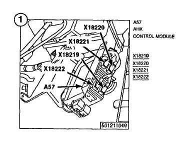
I would start to check AHK relay, it is powered by ignition (Front Power Distrubution Box) the contacts should close KL 30 and power the AHK Module (cable 2.5 colour green/White) distributed to AHK control module (12 Volts pin 7,8,17) later the reference voltage from the AHK moule 5 Volts x18221 and x18222 I cant see the pin numbers, sorry. Than check pins 17, 13, 7, 1 (Output pots reference voltages after the sensor). The AHK should be powered by ingnition on and you should see the 5 volts reference voltage coming from the AHK control module.
Member
I didn't took time to spend on my AHK trouble, I had to manage an annoying master/slave cylinders clutch issue (solved by replacing both master and slave cylinders).
I tried to measure voltage from control unit between pins 1 and 8, but I discovered there were four connectors, two blacks and two whites.
After some researches, I know this :
Connector location :
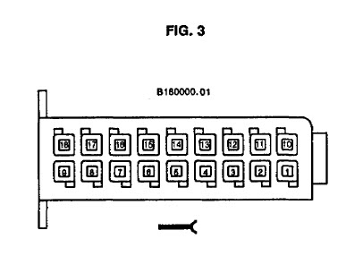
x18221 is white 18 pins
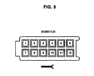
x18222 is white 12 pins
The pins are very little, it will not be easy to measure voltage.
I hope I will find time to perform the measures very soon.
Thank you again for your help and please accept my appologize for my low reactivity ;-)
PS: no way to measure voltage for pin 11 and 19 having connector plugged. The wires on the back of the connector are sealed with a kind of resine to avoid dust/rust (which is a good idea). The only way is to do measures on x18221/x18222 on the module.
Last edited by jules78; 09-29-2014 at 08:11 AM. Reason: need to add something
Member
Finally I took time to measure many many pins.
Here are the results :
AHK Relay K82 (ref BMW 00332014456 if someone needs to buy it)
OK. 12V present on cable 2.5 green/white with ignition on.
AHK Actuator.
(Test to see if potentiometer match their current position)
1198 Ohm between pin 6 and 19 (3.43V)
1118 Ohm between pin 9 and 11 (1.9V)
(Test to see if either are open/broken)
2200 Ohm between pin 6 and 7
2360 Ohm between pin 9 and 10
(Test potentiometer output voltage)
It's impossible to do this on the actuator itself because of sealed pins.
So I checked on the module after checking continuity between actuator and control module.
Pin 11 = pin 7 on x18222 -> 0.64V
Pin 19 = pin 13 on x18221 -> 3.14V
(Ground test)
Pin 7 -> 694 Ohm
Pin 10 -> 80 Ohm
Because ground on pin 10 was not good, I also checked pin 13 on x18220, ground was OK.
Reference voltage on Control module :
Pin 8 on x18222 -> 1.2V (cable Black/green)
Pin 16 on x18221 -> 5.06V (my cable is blue/gray like it should be on 840CI...)
I don't know what to think, but bad ground on pin 10 and bad reference voltage pin 8, maybe my control module is kaput ???
 Posting Permissions


 Reply With Quote
Bookmarks